


Most WebRTC material online jumps straight to code. That makes it hard to actually understand how WebRTC works or why certain components (like STUN, TURN, SDP, and ICE candidates) are needed. Here, we’ll break the technology down step-by-step so the logic behind WebRTC becomes clear.
By the end of this guide, you’ll know:
- Why browsers can communicate directly without plugins.
- Why direct peer-to-peer (P2P) streaming is not as simple as “just send video”.
- How NAT affects connectivity.
- What SDP and ICE candidates actually do.
- Why STUN and TURN servers are needed - and when.
⚙️ Want help building a WebRTC solution? Learn more about our WebRTC development services
Key Takeaways: Understanding WebRTC Basics
Media Streams
- Media streams bundle video and audio data.
- Tracks within a stream are synchronized, but different streams aren’t.
- Streams can be local (camera/mic) or remote (network input).
- Tracks can be enabled/disabled and consist of media channels, which are synced individually.
- Streams and tracks have labels to distinguish them.
Session Descriptors (SDP)
- SDPs establish a logical connection between nodes and contain codec and format info.
- Handshake uses offer → answer, and a local media stream is required for an offer.
- SDPs must be installed in WebRTC, whether received locally or remotely.
- Minor edits to SDPs are possible to fine-tune the connection.
ICE Candidates
- Candidates represent a node’s network address (own, router, or TURN server).
- Each candidate includes IP, port, and transport type (TCP/UDP).
- Only remote candidates are installed in WebRTC, usually after SDP installation.
- Candidates enable the physical connection between nodes.
NAT, STUN, TURN, ICE
- NAT allows internal devices to communicate externally via address and port mapping.
- STUN servers help nodes discover external IP/port and create NAT table entries.
- TURN servers act as relays if direct peer-to-peer connections fail.
What is WebRTC for?
WebRTC is a browser-oriented technology that allows real-time video and audio connections between clients without relying on external plugins like Flash. Its standout features are internal browser support and the ability to connect peers directly, without using an intermediate server.
The challenge comes from the fact that computers don’t always have public IP addresses. IPv4 addresses are limited, and for security reasons, NAT (Network Address Translation) was introduced. NAT allows multiple devices in a private network, like a home or office network, to share a single public IP. This is why many devices can access the internet via one router, even though each device has its own internal IP.
While NAT solves internal network management and security, it complicates peer-to-peer connections. Public IPs are unique, but private IPs aren’t. Let’s consider three scenarios to understand why:
1. Both nodes are within the same network.

2. Both nodes are in different networks (one private, one public).

3. Both nodes are in different private networks with the same internal IPs.

Let’s break these down.
Scenario 1: Same network
Here, nodes can directly connect using their internal addresses. There’s no conflict, and communication is straightforward.
Scenario 2: Different networks
In this case, routers come into play. Each router has two interfaces: internal and external. Internal addresses identify nodes within the network, while the external address represents the network to the outside world. For example, node p1 might have 192.168.0.200 as its internal IP and 10.50.200.5 as its external IP. Node p2 has a similar setup.
Using internal addresses alone won’t work because they are not visible outside the network. Using external addresses is possible, but tricky, because multiple nodes in the same network share that external IP. NAT helps here by mapping internal addresses to unique ports on the external address, allowing correct routing.
Scenario 3: Different private networks with overlapping IPs
If nodes with the same internal IP try to communicate, they would essentially talk to themselves. WebRTC handles this through the ICE protocol, which relies on STUN and TURN servers to bypass NAT limitations.
The Two Phases of WebRTC
WebRTC connections happen in two main phases:
Phase 1: Connection setup
Before any video or audio can flow, nodes need to exchange information about media streams, network addresses, and connection parameters. This is where signaling comes in. Signaling isn’t part of WebRTC itself - you can implement it via HTTP, WebSocket, or even SMTP. Its job is only to transmit the minimal required information: SDP (Session Description Protocol) and ICE candidates.
Phase 2: Media transmission
Once the connection is established, WebRTC handles actual video and audio transmission over TCP or UDP. Signaling is no longer needed during this phase; the peers communicate directly.
Connection Setup Steps
For the initiator (caller):
- Capture the local media stream (camera/mic) using getUserMediaStream.
- Create an offer for video transmission (createOffer).
- Receive the local SDP object and send it via signaling.
- Receive local ICE candidates and send them via signaling.
- Receive the remote media stream and display it (onAddStream).
For the receiver (callee):
- Capture the local media stream (getUserMediaStream).
- Receive the offer and create an answer (createAnswer).
- Send local SDP via signaling.
- Send local ICE candidates via signaling.
- Display the remote media stream (onAddStream).
Even though these steps look long, there are really just three actions: sending a local stream, exchanging connection parameters (SDP and ICE), and receiving the remote stream. The second step—exchanging connection parameters—is the trickiest because it involves setting up both logical and physical connections. The logical connection defines codecs and video/audio settings, while the physical connection establishes the packet path between nodes.
Main entities
MediaStream
A MediaStream is a core WebRTC entity that packages video and audio data for transmission. There are two main types: local streams, which capture data from input devices like cameras and microphones, and remote streams, which receive data from the network. In practice, every node typically has one local and one remote stream.
WebRTC provides a MediaStream interface to handle streams, along with a LocalMediaStream sub-interface for local streams. In JavaScript, you generally encounter only MediaStream, but libraries like libjingle also expose LocalMediaStream.
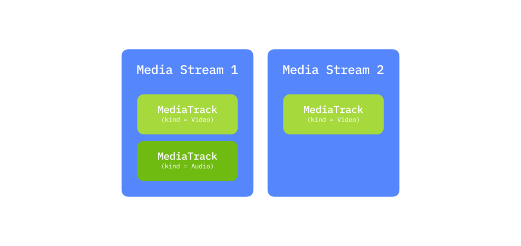
Streams have a hierarchical structure. Each MediaStream consists of media tracks (MediaTrack), and each track can contain multiple media channels (MediaChannel). You can also have multiple media streams simultaneously.
For example, suppose you want to transmit a video of yourself and a separate video of your desk while you write on a piece of paper. You would create two MediaStreams: one for yourself (with video and audio tracks) and one for the desk (video track only). These streams are independent because the content is not inherently synchronized.

Each media track has a kind attribute that specifies whether it carries audio or video. Inside a program, you would:
- Create the MediaStreams.
- Create video and audio tracks.
- Request access to the camera and microphone.
- Assign each track to the appropriate MediaStream.
Tracks are distinguishable by their labels, which identify the feature they correspond to. You could, in theory, transmit everything in a single stream with multiple tracks, but WebRTC tracks have a special feature: synchronization. Tracks within the same MediaStream are played in sync, while tracks across streams are independent. This means if you want your facial expressions, voice, and desk activity to play simultaneously, they must share a stream. If synchronization is less critical, separate streams make playback smoother.

Tracks can also be temporarily disabled using their enabled property.
Finally, media channels allow multiple audio channels - stereo or surround sound. A MediaTrack can use multiple channels (e.g., six channels for 5.1 surround), and channels within a track are synchronized. Video tracks usually use a single channel, but multiple channels can be used for special purposes, like advertisements.
Summary: A MediaStream is a container for video and audio data. Data is synchronized inside the stream. Streams contain one or more tracks, which may consist of multiple channels. In a simple video chat, you typically have one local MediaStream with a video track for the camera and an audio track for the microphone, each with a single channel.
Session descriptor (SDP)
Every computer has different cameras, microphones, and graphics capabilities. WebRTC coordinates all these parameters through a Session Description Protocol (SDP) object.
The SDP is transmitted to the other node via a signaling mechanism, which can be anything: WebSocket, HTTP, even manually over a phone call. The key point is that SDP carries configuration data, not the actual media. Once the remote node receives the SDP, it generates a response by calling createAnswer, creating its local SDP, which is then sent back via signaling.
Important rules:
- You must have a local media stream before calling createOffer or createAnswer. Otherwise, there’s no media to describe.
- createAnswer can only be called after receiving a remote SDP, because it relies on the remote parameters to coordinate codecs, resolutions, and other settings.
- Both local and remote SDP objects must be installed in WebRTC to finalize the configuration.
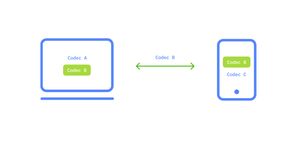
After this handshake, nodes know each other’s capabilities. For example, if node 1 supports codecs A and B, and node 2 supports B and C, they will agree to use codec B. At this stage, a logical connection is established, but the physical path for data transfer still needs to be set up.

ICE Candidates
Upon establishing a connection, the address of the node you need to connect with isn’t known. First, a logical connection is established, then a physical connection, although historically it used to be the other way around. It might seem strange, but this order makes sense if we remember that WebRTC uses an external signaling mechanism.
At this stage, the logical connection exists, but there is no usable path for transmitting data yet. Let’s start with a simple case. Imagine both nodes are within the same private network. They can easily connect via their internal IPs (or other addresses if TCP/IP isn’t in use).
WebRTC provides ICE candidate objects through callbacks. Like SDPs, they arrive as text and need to be sent to the other node via a signaling mechanism. While the SDP describes your media setup (camera, microphone, codecs), ICE candidates describe where the node is located in the network. Send them to the other node, and it can establish a logical connection. If the other node fails to send its candidate, you won’t be able to connect.
Unlike a classical client-server interaction, where a client sends a request and receives a response, WebRTC requires both nodes to know each other’s addresses. Only remote candidates need to be installed, editing them locally is prohibited. In most WebRTC implementations, candidates are installed after SDPs, because the logical connection must be ready before the physical path is created.
So why can there be one session descriptor but many candidates? A node’s network placement can involve its internal IP, external router addresses (possibly several), and TURN server addresses.
Let’s look at a simple example: within one network, we have two candidates. How do we identify them? Using the IP address, transport (TCP/UDP), and port. For instance, suppose we have port 531 and UDP transport.
When we’re inside the p1 node, WebRTC will give us a candidate object like [10.50.200.5, 531, udp]. If we’re inside p2, the candidate becomes [10.50.150.3, 531, udp]. Using a signaling mechanism, p1 receives p2’s IP and port and can send data directly to 10.50.150.3:531. It doesn’t matter whether the address belongs directly to p2 or to an intermediary; the data will reach the correct node.
Inside the same network, each node typically has one candidate (its placement in the network). But the number of candidates increases in more complex networks.
Consider a more complicated scenario: p1 is behind a router (NAT), while p2 is on the internet. Home routers maintain a NAT table to manage connections from internal devices to external servers. Suppose p2 has a public IP, and p1 sends a request to 10.50.200.10. The router receives the request at its internal interface (192.168.0.1), records p1’s internal IP in the NAT table, and substitutes the source IP with its external one. Then it forwards the request to p2.
When p2 responds, the router looks up its NAT table and forwards the packet to p1. If multiple internal nodes send requests, ports help the router distinguish between responses: it rewrites source ports for each internal device and uses them to route returning packets correctly.
Back to WebRTC: using ICE candidates, p2 has one candidate (10.50.200.10), while p1 behind NAT has two: a local candidate (192.168.0.200) and a router candidate (10.50.200.5). The local candidate is not useful here, but WebRTC generates it anyway. The router candidate is critical; its IP and port allow p1 to traverse NAT and reach p2.
NAT entries are only created when data leaves the internal network, which is why p1 must send something first. Once p2 responds, the NAT tables on both routers have the necessary entries, and the connection can proceed.
Finally, if both nodes are behind NAT, creating entries in both NAT tables requires sending data through a public network node. That’s why WebRTC uses STUN and TURN servers connected to the internet—they help nodes discover external IPs and relay data when direct connection is impossible.
STUN and TURN servers
When initializing a WebRTC connection, you must specify STUN and TURN servers - from now on referred to as ICE servers. If these servers aren’t mentioned, only nodes on the same local network (without NAT) will be able to connect. This is why, for example, 3G networks require TURN servers to function properly, as direct peer-to-peer paths are often blocked.
A STUN server is a server on the internet that helps a node discover its external IP address and port. A node behind a router (NAT) communicates with a STUN server to bypass NAT restrictions. When a packet reaches the STUN server, it contains the source address, which is usually the router’s external IP and port. The STUN server returns this address to the node, allowing it to create an additional ICE candidate. This candidate now contains an address that other nodes can use to reach the hidden node. Behind the scenes, the router updates its NAT table to make sure incoming packets with that external port are forwarded to the correct internal node.
How a STUN server works
Let’s take a simple setup:
- Node: p1
- Router: r1
- STUN server: s1
- Router’s NAT table: r1_nat
Initially, the NAT table is empty:

Now p1 sends a packet to s1. The packet header includes source and destination addresses:

The router substitutes the source IP and source port with its external IP and a new port for NAT tracking. Let’s say the router chooses port 888.
The modified packet header:

The NAT table now records:

Here, 10.50.200.5 is r1’s external IP. When the STUN server receives this packet, it sees 10.50.200.5:888 as the sender and returns this address to p1. Once p1 receives it, it knows exactly which external IP and port other nodes can use to reach it.
The return packet from s1 swaps source and destination:

The content of the packet contains 10.50.200.5:888, which p1 uses to create a new ICE candidate. When this packet passes back through r1, the NAT table ensures it’s forwarded to 192.168.0.200:35777, completing the path. Now p1 is reachable from outside, despite being behind NAT.
TURN Server
A TURN server is like a STUN server with a relay capability. If direct peer-to-peer communication is impossible, for example on symmetric NATs or mobile networks with strict firewalls, the TURN server relays packets between nodes. WebRTC nodes behave as if they are directly connected, but the TURN server forwards the data.
Why might TURN be necessary? Some NAT types, especially symmetric NAT, store not just the internal IP and port, but also the remote peer’s IP and port. In these cases, packets from a peer cannot traverse NAT unless they originate from the exact same source as the initial STUN-discovered path. A TURN server circumvents this limitation.
In short, while every TURN server can act as a STUN server, the reverse isn’t true. TURN servers ensure connectivity when direct peer-to-peer paths are blocked or impossible, guaranteeing that WebRTC communication works reliably across different networks.
WebRTC FAQ
What is WebRTC?
WebRTC (Web Real-Time Communication) is a technology that allows browsers and apps to transmit audio, video, and data in real time without requiring additional plugins or software. It powers video calls, chat apps, and live streaming.
Do I need to install anything to use WebRTC?
No. WebRTC is built into modern browsers, so users don’t need to install anything extra. Developers may need libraries or SDKs for more complex features.
How does WebRTC handle different networks?
WebRTC uses ICE (Interactive Connectivity Establishment), STUN, and TURN servers to manage connections across networks, including those with firewalls or NAT routers. STUN finds your public IP, while TURN relays data if a direct connection isn’t possible.
What are media streams and media tracks?
Media streams are containers for audio and video data. Each stream consists of tracks, one for audio and one for video, which can be turned on or off individually. Tracks are synchronized within a stream but not across streams.
How secure is WebRTC?
WebRTC encrypts audio, video, and data using secure protocols (SRTP and DTLS). This ensures that communication remains private between participants.
How can WebRTC benefit my business?
WebRTC allows businesses to implement real-time communication without costly infrastructure. It enables customer support via live chat/video, internal collaboration, remote consultations, and interactive marketing - all directly through a browser or app.
Wrapping Up
WebRTC may seem complex at first, but understanding media streams, SDPs, ICE candidates, and NAT traversal gives you the foundation to build robust real-time communication apps and choose the best part for your communication app.
⚙️ Learn more about our WebRTC development services
💡 Ready to bring real-time video and audio into your app? Get these integrated fast – reach out or book a consultation today to get expert guidance.


