


Why this matters
If you build, operate, or buy WebRTC software — a conferencing product, a telemedicine room, an e-learning live class, a contact-centre video channel, a live-shopping floor, a remote-collaboration tool, or an AI-agent voice-and-video service — your product's user experience is essentially set by how well bandwidth estimation works on the worst networks your viewers are on. When the estimator over-shoots, frames freeze, audio cracks, and call-quality dashboards light up red. When it under-shoots, the picture stays soft, the screen-share blurs, and the room feels low-rent even though plenty of bandwidth was available. Engineers tune this loop for a year and product managers ship the result for a decade. The point of this article is to give the non-network-engineer the same mental model the WebRTC engineers carry: what the loop measures, what it decides, where it is conservative, where it is wrong, and what you can change to nudge it.
The control loop in one paragraph
Imagine you are pouring water into a hose and you cannot see the other end. You start gently. After a moment, a friend at the far end calls back and tells you whether the water is arriving on time, late, or not at all. You speed up if the answers stay clean and slow down the instant they slip. A WebRTC sender does exactly that, ten to twenty times a second, with packets instead of water and an RTCP feedback message instead of a friend. The sender writes a sequence number into every outgoing RTP packet, the receiver writes back a compact RTCP report listing those sequence numbers with timestamps showing when each packet arrived, and the sender's congestion controller compares those arrival times to the times it sent the packets. If the gap between sending and arrival is growing, the network is filling up — back off. If the gap stays flat and no packets are lost, the network is fine — push up gently and see if the answer changes. That loop is the entire game. Everything else in this article is the detail of how that game gets played correctly under real-world packet loss, mobile-radio jitter, NAT-rebinding events, sudden cross-traffic, and the ten-thousand-line code base that ships inside every Chromium build. (For the wider transport context, see TCP, UDP, and the choice every streaming protocol must make and Congestion control in plain English: BBR, CUBIC, Copa.)
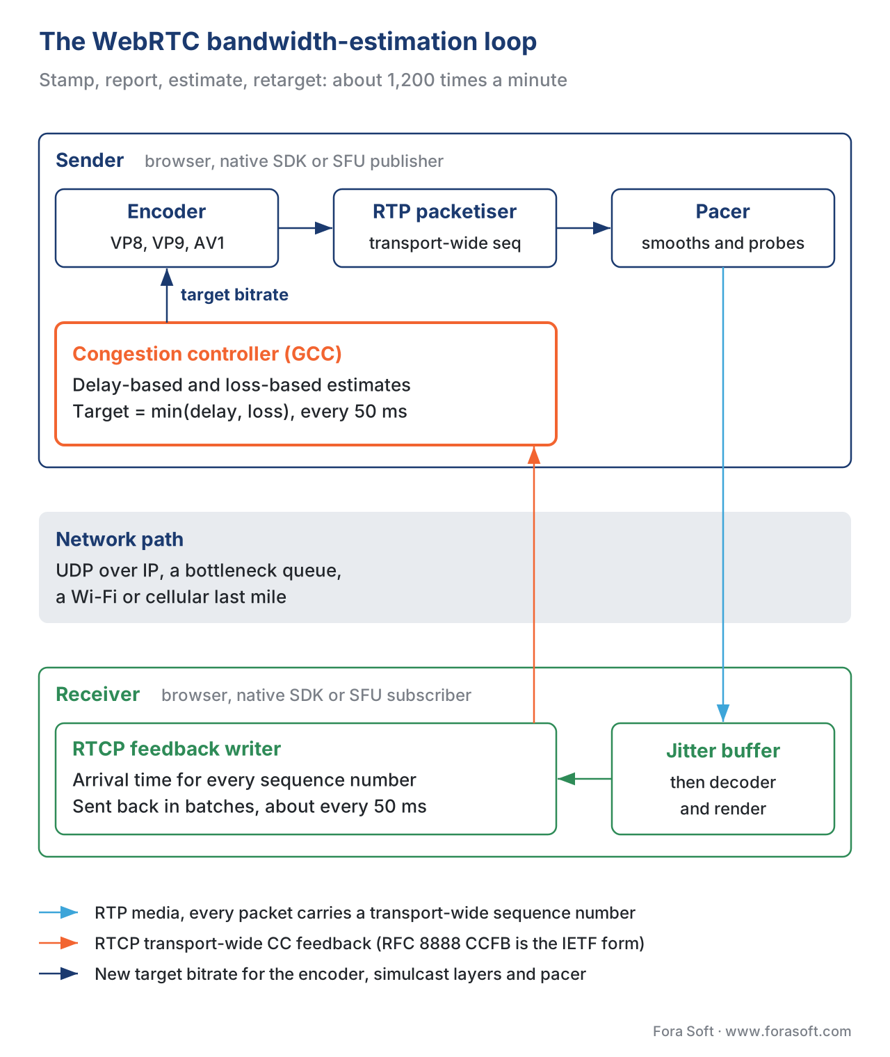 Figure 1. The WebRTC congestion-control loop. The sender writes a transport-wide sequence number on every outgoing packet; the receiver writes back arrival timestamps; the sender estimates available bandwidth from the time series and tells the encoder what to target. The loop runs continuously for the lifetime of the call.
Why a media call needs its own congestion controller
A web page transferring a file over HTTP runs on TCP and inherits TCP's congestion control — usually CUBIC, sometimes BBR, sometimes Reno (see the wider transport-protocol overview in Congestion control in plain English: BBR, CUBIC, Copa). A WebRTC media call deliberately does not. The reason is that TCP's response to packet loss is to retransmit the lost bytes in order, which produces head-of-line blocking — newer bytes wait behind older ones until the older ones arrive. For a file download that is the right trade-off: a corrupted spreadsheet is worse than a slow one. For real-time video it is the wrong trade-off: a 200-millisecond delay caused by a TCP retransmit will make the audio audibly choppy and the video visibly stuttery, and a one-second delay will end the conversation. So WebRTC media runs on UDP, packaged as RTP with SRTP encryption (see DTLS, SRTP, TLS, mTLS for media), and the WebRTC engine has to do congestion control itself instead of letting TCP do it. The congestion controller's job is to decide how fast the application is allowed to send media, which the application then enforces by either lowering its encoder's target bitrate, dropping simulcast layers, or pacing the packets out more slowly.
The trade-off the controller makes is different from TCP's too. TCP optimises for throughput: get as many bytes through as possible. A WebRTC controller optimises for low end-to-end latency at acceptable quality, even if that means leaving headroom on the table. That difference is why the standard WebRTC stack will not push as hard against a bottleneck as a parallel file download would; the call has different goals than the download, and the controller respects them.
The signal: what every packet carries
For the loop to work, the sender needs the receiver to be able to identify which packet arrived when. RTP sequence numbers exist (16 bits, per-SSRC, defined in RFC 3550) and they are enough to detect loss, but they do not let the receiver report a single timeline across multiple media streams in the same transport. In a typical call, the sender pushes an audio stream and a video stream — sometimes simulcast video with three resolutions, sometimes a screen-share track, sometimes Scalable Video Coding (SVC) layers — and the controller wants to reason about all of them together because they share the same network bottleneck. That is the job of the Transport-Wide Congestion Control header extension.
The transport-wide sequence number
The sender attaches an RTP header extension called transport-wide-cc-02 to every outgoing packet on the connection. The extension carries a 16-bit number that increases by one for every packet sent on that transport, regardless of which SSRC the packet belongs to. The format is documented at the WebRTC project's own site under transport-wide-cc-02: two bytes of extension ID and length, two bytes of transport sequence number, four bytes total. Because the number is transport-wide and not per-stream, the receiver can write a single arrival-time series across audio, video, simulcast layers, and any other SSRC sharing the transport — and the sender can then reason about a single network path instead of one path per SSRC.
A predecessor extension called abs-send-time (abs-send-time on the WebRTC site) carries the sender's transmission timestamp at 24-bit resolution and is what the receiver-side REMB feedback (described below) reads. Modern senders almost always negotiate both — abs-send-time for backward compatibility with REMB receivers, transport-wide-cc-02 for the modern feedback path. Both are SDP-negotiated; if the receiver does not signal support for transport-wide-cc-02, the sender falls back to the older REMB-based path.
The receiver's feedback
The receiver sends back an RTCP packet that lists, for a batch of transport sequence numbers, when each packet arrived (relative to a base time) and whether it arrived at all. The format is the Transport Wide CC Feedback message — Google's invention, never standardised at the IETF as an RFC but documented in draft-holmer-rmcat-transport-wide-cc-extensions-01 and shipped in every libwebrtc-derived implementation. The feedback rate is configurable but typically lands at about every 50 ms for video, batching up the transport sequence numbers seen since the previous feedback. The result is a high-frequency time series the sender can act on.
A second, older feedback message — the Receiver Estimated Maximum Bitrate, REMB (defined in draft-alvestrand-rmcat-remb-03) — is still used by some receivers. In a REMB world, the receiver runs the delay-based estimator on its own and writes back a single number: "send no more than X bits per second on this stream". The sender obeys. In a Transport-Wide CC world, the receiver only ships the timestamps and the sender runs the estimator. The latter is the modern default because the sender can correlate the timestamps with information it alone has — what it was trying to send, what the encoder produced, whether a probe packet was in flight — and produce a better estimate.
The IETF-standardised alternative: RFC 8888 CCFB
In 2020 the IETF published RFC 8888, the RTP Control Protocol (RTCP) Feedback for Congestion Control message. RFC 8888 is, conceptually, the same thing as Transport-Wide CC Feedback: a compact RTCP message that returns per-packet arrival information to the sender so the sender can run a congestion controller. The differences are in the bits: RFC 8888 reports per-SSRC instead of transport-wide, includes an explicit ECN-CE (Explicit Congestion Notification) marking field that lets the sender react to ECN signals (essential for the L4S story; more below), and has a published RFC behind it. The WebRTC source code documents this explicitly: the transport-wide CC extension cannot be used at the same time as the RFC 8888 CCFB feedback format. As of 2026, RFC 8888 support is shipping in some implementations but not yet the libwebrtc default; the migration is gradual.
The math: how arrival timestamps become a bitrate
At this point the sender has, every 50 ms or so, a list of transport sequence numbers it sent and the times each one arrived. Two estimators run on that list in parallel. Their outputs are combined; the final bitrate sent to the encoder is the lower of the two.
Estimator 1 — delay-based
The delay-based estimator is the heart of Google Congestion Control. The current canonical reference is the (now-expired) Internet-Draft draft-ietf-rmcat-gcc-02 (Holmer, Lundin, Carlucci, De Cicco, Mascolo, July 2016); the algorithm in the libwebrtc source has evolved since but the structure is the same one the draft describes.
The intuition is this. If the network is not congested, the gap between two packets at the receiver equals the gap at the sender — packet A leaves at t, packet B leaves at t + 10 ms, both pass through an empty queue, both arrive 10 ms apart. If the network is starting to congest, packet B arrives later than its expected 10-ms gap because it had to wait in a queue. The estimator measures the inter-arrival-time delta — the arrival-time gap minus the send-time gap, sometimes called the one-way delay variation — and feeds it into a Kalman filter that estimates a slow-moving signal: how much is the queueing delay trending? An adaptive threshold (the controller adjusts the threshold itself as the network changes) classifies the trend as one of three states: under-using (gap is shrinking — speed up), normal (gap is flat — hold), over-using (gap is growing — back off). The state drives a rate controller that ramps the bitrate up multiplicatively when "under-using", holds it when "normal", and drops it (multiplicatively, around the current incoming rate measured at the receiver) when "over-using".
A worked example, in slow motion. Say a sender is sending at 1,200 kbps. It sends a 1,250-byte video packet at sender time 100,000 µs and a 1,250-byte packet at 110,000 µs (10 ms gap). The receiver records them at 100,300 µs and 110,330 µs (10.03-ms inter-arrival gap on its clock; the 300-µs base offset is irrelevant to the controller). The inter-arrival delta is 10.03 ms − 10 ms = 30 µs — basically nothing. The filtered trend stays close to zero, the threshold says "normal", the controller holds. Now a cross-traffic flow kicks in and the bottleneck queue starts filling. The next pair has a sender-side gap of 10 ms but an arrival gap of 13 ms — a 3-ms delta. After a few such samples in a row, the Kalman filter's estimate of the trend crosses the threshold, the state changes to "over-using", and the controller multiplies the target rate by a backoff factor — typically 0.85 of the current incoming receive rate, around 1,000 kbps in this example — and tells the encoder. The encoder drops its next frame's target QP or skips a frame, the sending rate falls to 1,000 kbps, the queue drains, the next samples come back to a near-zero delta, the state returns to "normal", and after a few seconds of "normal" the controller starts ramping up again — multiplicatively, typically by a factor in the 1.05–1.08 range per RTT — looking for the new bottleneck rate.
The whole loop runs once per feedback packet (~50 ms). Over a one-minute call the controller will make 1,200 separate decisions about the target bitrate. The encoder gets a new target bitrate from the controller through the libwebrtc Call::OnBitrateAllocationChanged interface (or equivalent in other stacks); the encoder either re-encodes the next frame with the new target or, in simulcast, switches which layer it is transmitting (see Simulcast and SVC in the SFU for what the layer switch looks like from the SFU's side).
Estimator 2 — loss-based
The delay-based estimator is good but blind to one failure mode: a lossy link where packets are dropped before they ever queue. A radio link with a weak signal, a Wi-Fi link with collisions, a satellite link in heavy weather — these often have low base-level delay (because the queues are small) but lose 2–10% of packets at random. The delay-based estimator on its own would happily push the rate up because its delay samples look clean.
The loss-based estimator catches that case. It reads the same RTCP feedback (which packets did and did not arrive), computes a loss ratio over a rolling window, and applies thresholds: below 2% loss, the loss-based estimator is happy and outputs a high "safe" bitrate; above 10% loss it slashes the bitrate to roughly half of the current sending rate; between 2 and 10% it linearly interpolates. The final bandwidth estimate the encoder uses is min(delay-based, loss-based). The loss-based component is the safety net for the lossy-but-not-congested case.
The loss-based BWE itself has evolved across three generations inside libwebrtc, as Gustavo García's webrtcHacks summary catalogues (Loss-based bandwidth estimation in WebRTC): the original "thresholds and step changes" version from 2011, a "smoothed thresholds and trends" v1 from around 2019, and a "maximum-likelihood from candidate rates" v2 introduced in 2023. The v2 model in particular is what production stacks ship in 2026; it formulates the loss-rate-as-a-function-of-sending-rate relationship probabilistically and picks the sending rate that maximises the joint likelihood of observed loss and observed acknowledged rates. The change matters most on flaky cellular links where the older versions used to over-shoot or under-shoot dramatically.
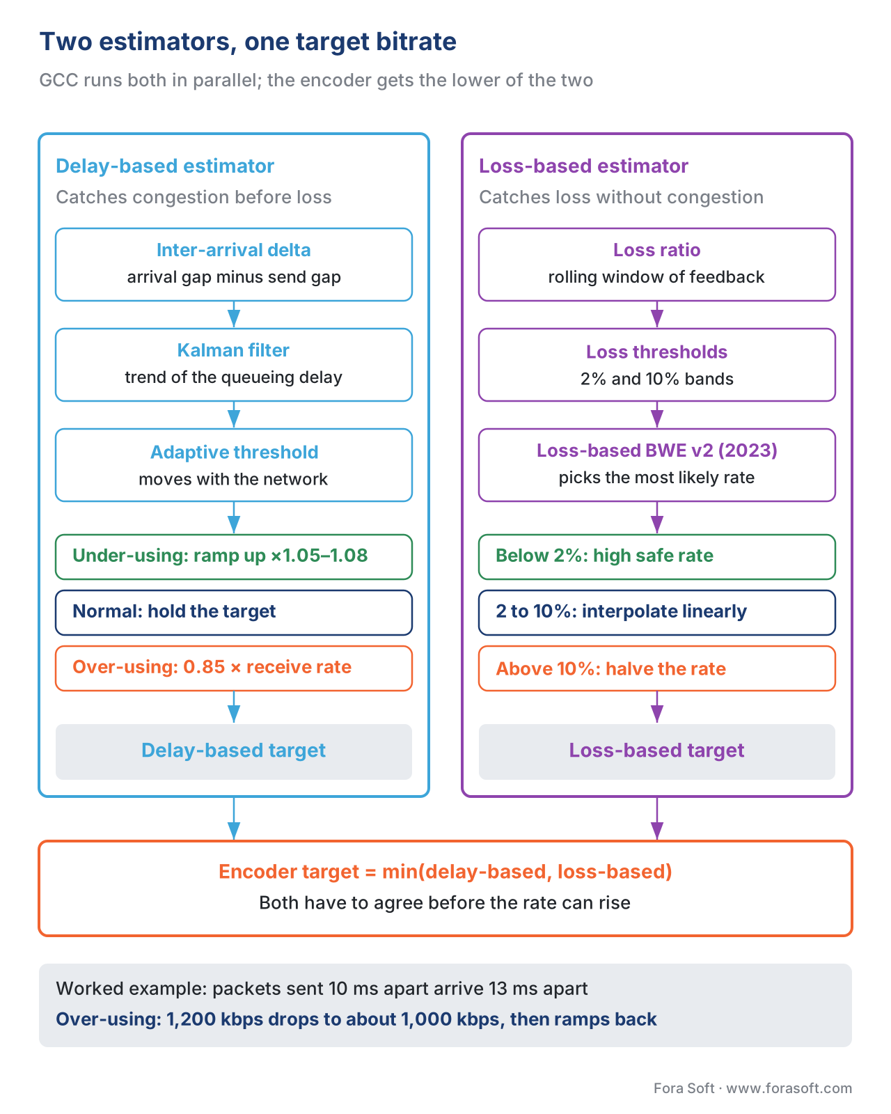 Figure 2. The two estimators inside libwebrtc's Google Congestion Control. The delay-based estimator handles congestion before loss appears; the loss-based estimator handles loss without congestion. The final target is the min — both have to agree before the rate can rise.
Probing: the third trick
A controller that only reacts to what the encoder is already sending has a problem: it cannot tell the difference between "the encoder is sending 800 kbps and the network is fine with that" and "the encoder is sending 800 kbps and the network could carry 8,000 kbps". The rate signal is bounded above by the encoder's output. To find the ceiling, the controller has to occasionally send more than the encoder is producing, see whether that extra traffic also arrives on time, and ramp up the encoder if it does.
This is what bandwidth probing does. The controller injects a short burst of padding packets — typically a 100-ms-or-shorter burst at a deliberately higher rate than the encoder's current target — and watches the feedback. If the burst's packets arrive with the same near-zero one-way delay variation as ordinary traffic, the network has headroom; the controller raises its target. If the burst's packets pile up, the network does not; the controller leaves the target alone. The probe payload is fed from the SFU's own padding bytes or, in some stacks, by duplicating an existing RTP packet stream. The exact behaviour and history is documented at webrtcHacks's Probing WebRTC Bandwidth Probing and in the libwebrtc source under modules/pacing/bitrate_prober.cc.
Probing is what makes start-up fast. Without it, a call would have to grow from the initial bitrate (usually 300 kbps for video) up to the ceiling by waiting for the encoder to output more bits — which the encoder will not do until the controller tells it to. With probing, the controller can drive a burst at, say, 2,000 kbps within a few hundred milliseconds of the call starting, the feedback confirms the path is clean, and the encoder is told to jump straight to 2,000 kbps. The end-user-visible effect is the picture sharpening within the first second instead of taking ten.
The alternatives: SCReAM and NADA
The IETF Real-time Multimedia Application coordination working group (RMCAT) published three algorithms in the 2017–2019 timeframe: Google Congestion Control as an Internet-Draft, SCReAM as RFC 8298, and NADA as RFC 8698. All three target the same problem and use the same RTCP feedback signals. They differ in algorithm shape and in what they optimise.
SCReAM (Self-Clocked Rate Adaptation for Multimedia) is Ericsson's algorithm and was designed with mobile radio links in mind. It is window-based (it tracks how many bytes are "in flight" against a congestion window, the way TCP does) rather than purely rate-based, and it is hybrid loss-and-delay. The window-based nature makes it self-clocked: the sending rate is implicit in the window and the round-trip time, so the algorithm does not need an explicit pacing target. SCReAM has shipped in some production RTC stacks (notably Ericsson's own; there is a public reference implementation at EricssonResearch/scream) and in 2026 a v2 update is in progress at draft-johansson-ccwg-rfc8298bis-screamv2-03.
NADA (Network-Assisted Dynamic Adaptation) is Cisco's algorithm. It is a rate-based controller built to use Explicit Congestion Notification (ECN) markings if they are available, falling back to delay and loss when they are not. ECN lets a network device mark a packet's IP header bit instead of dropping the packet when its queue starts to fill; the receiver echoes the mark back, and the sender slows down without ever losing the data. NADA is the algorithm best-positioned for the L4S (Low Latency, Low Loss, Scalable Throughput) story — the family of standards published as RFC 9330–9332 — because L4S relies on ECN. Where ECN is not available, NADA reverts to delay and loss like the other two.
The comparison most engineers care about: which one ships in browsers? In 2026 the answer is unchanged from a decade ago: Chrome, Edge, Safari, and Firefox ship Google Congestion Control because libwebrtc ships it. The standardised algorithms (SCReAM, NADA) ship in a small number of specialised stacks and in research papers. This matters because the entire browser-to-browser, browser-to-SFU, and SFU-to-browser ecosystem inherits GCC's behaviour. If your product runs through a browser at any point, GCC's quirks are your quirks.
Comparative table
| Property | Google Congestion Control (GCC) | SCReAM (RFC 8298) | NADA (RFC 8698) |
|---|---|---|---|
| Algorithm shape | Rate-based, delay + loss, min(delay, loss) | Window-based, hybrid delay + loss | Rate-based, delay + loss + ECN |
| Standards status | Expired IETF draft (draft-ietf-rmcat-gcc-02, 2016); de-facto standard in libwebrtc | IETF RFC 8298 (Feb 2018); v2 bis in progress 2026 | IETF RFC 8698 (Feb 2020) |
| Feedback message | Transport-Wide CC Feedback (Google-defined) or REMB legacy | RFC 8888 CCFB | RFC 8888 CCFB |
| Reacts to ECN | No (planned via L4S work) | Optional | Yes (designed for it) |
| Production deployment | Chrome / Edge / Safari / Firefox / libwebrtc-derived SDKs / every major SFU | Ericsson reference; a few specialised stacks | Research and specialised stacks |
| Mobile-radio behaviour | Good in v2 loss-based estimator | Designed for it | Designed for it |
| Where used in 2026 | Every browser-based WebRTC call | Some Ericsson-stack deployments; research | L4S-enabled networks; research |
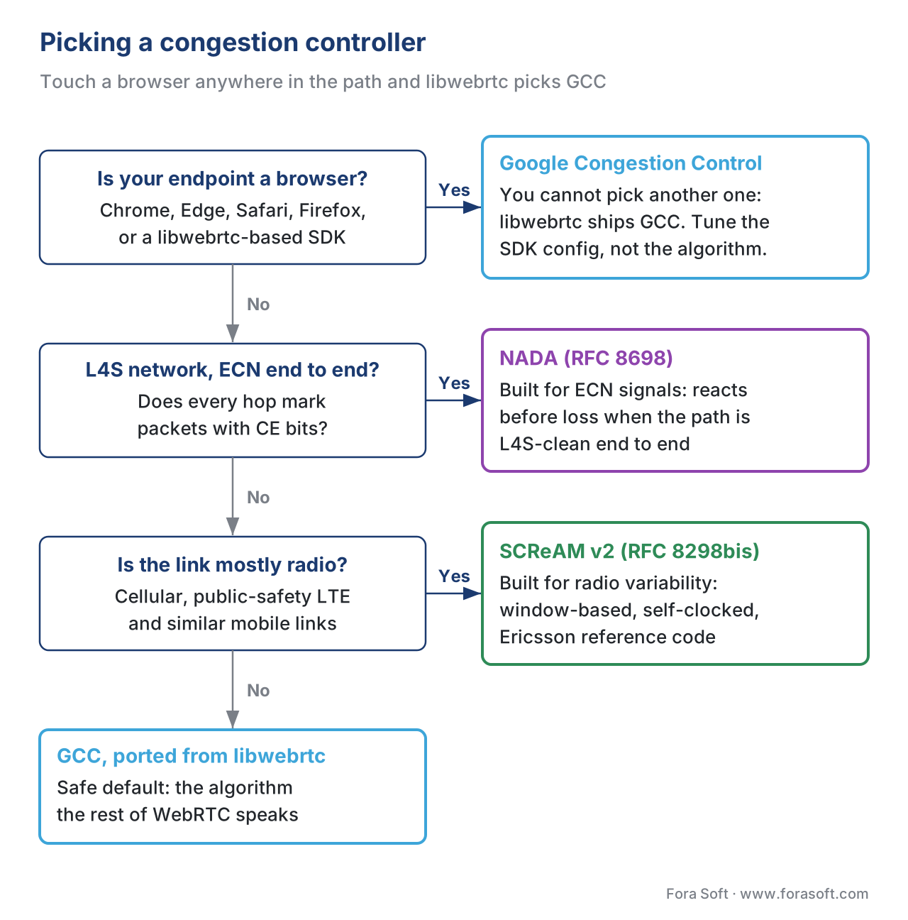 Figure 3. Picking an RTC congestion-control algorithm in 2026. For the overwhelming majority of products that touch a browser anywhere in the path, the choice is made for them by libwebrtc.
What the encoder actually does with the number
A congestion controller producing target bitrates is only half of the story. The encoder, the simulcast or SVC layer manager, and the pacer have to convert that number into actual on-the-wire behaviour.
The encoder is told a new target rate and reacts on its next frame. For single-stream WebRTC video — one publisher, one resolution, one bitrate — the encoder rerates: a libvpx VP8 or libvpx-vp9 encoder with rc_target_bitrate updated will produce its next frame at the new rate, usually adjusting the quantisation parameter (QP) to hit the target. Quality drops smoothly with bitrate down to a minimum where the encoder switches behaviour and starts dropping frames instead of further increasing QP — typically around 150–250 kbps for 720p video.
For simulcast video, the controller does not tell the encoder a single number; it tells the simulcast layer manager an overall budget, and the layer manager chooses which combination of simulcast layers fits. A typical libwebrtc client publishes three layers: 720p at 1,500 kbps, 360p at 500 kbps, and 180p at 150 kbps. If the total target is 1,500 kbps, the manager publishes all three. If the target drops to 700 kbps, the manager drops the 720p layer and publishes only the 360p and the 180p — total 650 kbps, fits inside the budget with margin. If the target drops further to 200 kbps, only the 180p layer is published. The drop is sharp at each step, which is one reason simulcast quality can look "stepped" rather than smooth as the network degrades. (For the full simulcast story, see Simulcast and SVC in the SFU.)
In a Selective Forwarding Unit (SFU) deployment, the SFU itself runs a per-subscriber bandwidth estimator on the downlink to each subscriber and chooses which simulcast layer to forward to that subscriber. The mediasoup project documents this directly: the estimated outgoing bitrate (from REMB or Transport-Wide CC feedback) is distributed across the consumers, prioritising higher-priority tracks. LiveKit's architecture documentation describes the same pattern: client SDKs publish three simulcast layers by default and the SFU picks the layer per subscriber based on REMB and TWCC signals from each downlink (LiveKit architecture deep dive). The same loop runs twice — once between the publisher and the SFU, once between the SFU and each subscriber — so a misconfigured bandwidth-estimation path on the SFU's downlink can wreck the experience even when the uplink is fine.
The pacer, finally, is the thing that converts a target bitrate into actual packets-on-the-wire spread out over time. Without a pacer, a 30-fps encoder producing 1-Mbps video would send the entire frame's bytes in a single burst at frame time, then idle for 33 ms, then burst again. That burst pattern is bad for the controller: it inflates queueing delay artificially and confuses the delay-based estimator. The libwebrtc pacer (in modules/pacing/) smooths the outgoing rate by holding packets in a queue and releasing them at the target rate, so the network sees a roughly constant flow instead of bursts. The pacer also holds the probing logic — when the controller wants to probe, the pacer is what actually injects the extra packets.
What you can read from getStats()
Every modern WebRTC implementation exposes the inside of this loop through the W3C RTCPeerConnection.getStats() API. The relevant fields, as specified in the W3C webrtc-stats Candidate Recommendation, are on the outbound-rtp and remote-inbound-rtp reports:
outbound-rtp.targetBitrate— the bitrate the controller is currently asking the encoder to hit. This is the closest thing to "the bandwidth estimate" in a single number.outbound-rtp.totalEncodedBytesTarget— the cumulative target across the call; rate of change is the recent target.remote-inbound-rtp.fractionLost— the loss fraction the receiver reports back over the latest interval. Feeds the loss-based estimator.remote-inbound-rtp.roundTripTime— RTT samples from RTCP. Useful for sanity-checking the controller's reactivity.candidate-pair.availableOutgoingBitrate— what the controller is willing to send right now, including any headroom set aside for probing.
If you are debugging "why is the picture so soft" — pull targetBitrate and fractionLost from getStats() once a second, plot them, and you will usually see the answer within the first 30 seconds of the call. A target that is hovering at 250 kbps despite a clean network usually means a min-bitrate configuration somewhere is set too low. A target oscillating between 2,000 and 400 kbps every five seconds usually means the loss-based estimator is reacting to a transient burst of loss. A target that climbs steadily from 300 kbps to 1,500 kbps over the first ten seconds and then stays put is the loop working correctly.
Where it breaks in real deployments
The loop is robust in the lab and fragile in the field. The most common production failure modes:
- Slow start at call setup. The initial target is conservative (libwebrtc defaults to 300 kbps for video). Without effective probing — which requires a clean path and a few RTTs of measurement — the rate climbs slowly. A call that should be at 2 Mbps is at 600 kbps thirty seconds in. The fix is to enable probing aggressively in the publishing SDK and to set a higher
min-bitrateif you can justify it. (LiveKit'sdynacastfeature solves a related problem by pausing layers no one is subscribed to and only ramping when a subscriber appears, see Bringing Zoom's end-to-end optimizations to WebRTC.) - Wi-Fi to cellular hand-off. The active path's properties change abruptly: latency doubles, available bandwidth drops by an order of magnitude, the bottleneck moves to the radio. The loop's reaction is delayed by one RTT plus the feedback interval — typically 100–200 ms — during which the encoder is over-shooting hard. The result is a one-to-two-second freeze. The mitigation is to detect the path change at the ICE layer (see NAT, STUN, TURN, ICE for WebRTC) and pre-emptively drop the target rate before the new path is confirmed, instead of waiting for feedback.
- Bufferbloat on a residential router. A consumer Wi-Fi router with a 500-ms FIFO queue will absorb a lot of over-shooting before it starts dropping packets, masking congestion from the loss-based estimator while inflating one-way delay massively. The delay-based estimator catches it, but only after the queue is already deep — and once it is deep, the audio cracks because audio packets are stuck behind video bytes. Mitigations are on the network side (Active Queue Management like CoDel, or L4S/ECN end-to-end if the path supports it); from the application side, the only lever is to keep the controller's headroom conservative on networks the application knows are residential.
- Cross-traffic from a parallel TCP download. A streaming-TCP flow (Netflix, YouTube, a background app update) on the same uplink will push as hard as it can, while the WebRTC controller deliberately backs off. WebRTC's rate falls because GCC sees the queue growing; the TCP flow sees nothing and keeps pushing. Result: the call quality collapses while the download stays fine. This is the well-documented "real-time vs bulk fairness" problem and there is no protocol-level fix; it requires either a network-level fix (the same AQM and L4S story as above) or a product-level fix (warn the user to pause downloads during the call).
- Asymmetric paths and the wrong feedback direction. The feedback packets themselves take a path that may be different from the forward path. If the feedback path congests, the sender's feedback is delayed and stale; the controller's reactions are out of date. In practice this is rare but it does happen on satellite uplinks and certain TURN-relay configurations. The diagnostic is a growing
roundTripTimefrom the feedback side while the forwardavailableOutgoingBitratelooks fine. - The SFU's downlink is the bottleneck and the publisher cannot help. A publisher with a fat uplink is publishing three simulcast layers at 2,500 kbps total to an SFU. A subscriber on a slow downlink can only handle 700 kbps. The SFU's per-subscriber estimator drops to the lowest simulcast layer (180p at 150 kbps) for that subscriber — but the subscriber sees a soft 180p picture even though, in principle, a 360p picture is also being published. The fix is either an SFU that runs SVC instead of simulcast (so any subscriber can get any layer's bytes), or a publisher SDK that re-rates based on the worst subscriber's downlink. (The mediasoup, LiveKit, Janus, and Jitsi Videobridge teams have all written about variants of this trade-off; see SFU comparison: mediasoup, Janus, LiveKit, Jitsi, Pion.)
Common mistake: tuning the encoder's bitrate caps without tuning the controller's
A frequent mis-configuration in WebRTC products is setting RTCRtpEncodingParameters.maxBitrate to a high value (5 Mbps for a 720p simulcast layer, say) in the hope of "letting the call use more bandwidth on a good network". The controller will not honour that ceiling unless it has independently estimated that the network can carry it, so on most networks the encoder is capped by the controller's estimate, not by maxBitrate. Where the misconfiguration does bite is on the rare network where the controller's estimate runs ahead of the actual bottleneck — at which point the encoder is pushing 5 Mbps into a path that cannot carry it, the queue blows up, the audio cracks, and the call falls apart. The cure is to set maxBitrate to a value that reflects the call's purpose (1,500–2,500 kbps for typical 720p conferencing) and let the controller stay below that ceiling. Raising the ceiling beyond what the call genuinely needs is asking for trouble.
The 2026 frontier: machine learning, L4S, and AI agents
Three changes are landing in production this year and next, in order of how mature they are.
Machine-learning–assisted estimators. Meta published Optimizing RTC bandwidth estimation with machine learning in early 2024 describing a learned controller deployed in Messenger and WhatsApp video calls; the model produces the same target-bitrate signal as GCC but is trained on per-call telemetry rather than on hand-tuned thresholds. The team reports measurable quality wins on the long tail of poor networks. Several vendor stacks (LiveKit, Daily, others) are experimenting with similar models; the open-source libwebrtc is still GCC. Watch this space.
L4S and ECN end-to-end. L4S (RFC 9330–9332, March 2023) is the network-side change that, if deployed end-to-end, can collapse queueing delay to near-zero while still using the link's full capacity. The story is that a queue-aware AQM at the bottleneck marks ECN-CE on packets when the queue starts to fill instead of dropping them; the sender slows down on the mark, and the queue never grows enough to add latency. WebRTC stacks are beginning to support reading ECN marks through RFC 8888 feedback. A recent ACM paper, Lag-Busting WebRTC: L4S-Enabled Adaptive Video Streaming, demonstrates an L4S-enabled WebRTC video path with notably better delay-quality trade-offs. The catch is that L4S only helps if every hop on the path supports it, which is a slow ecosystem build-out.
AI agents and the "talking on behalf of a model" workload. A new workload that arrived in volume in 2025 is the LLM-powered voice agent: a real-time WebRTC session between a human and a server-side model, with low-latency audio in both directions and often a video track too. The agent's traffic profile looks different from a human conferencing call — the bursts of speech are model-generated and often steadier, the silence gaps are predictable, and the network paths often run between a colocated data centre and a residential consumer. Several stacks are beginning to specialise the controller for that workload; the LiveKit team has written about it in the LiveKit agents announcement. The implications for bandwidth estimation are not yet fully worked through in standards bodies, but in practice the workload is becoming a non-trivial driver of new BWE work.
Free download: WebRTC Bandwidth-Estimation Tuning Checklist30 items to verify the BWE loop before you ship: control signal, encoder, probing, SFU downlink, failure-mode tests and observability.Where Fora Soft fits in
Fora Soft has shipped WebRTC since 2010, when WebRTC itself was still a Chrome flag. Across video conferencing, telemedicine, e-learning, live-shopping, and AR/VR projects, our teams have tuned the bandwidth-estimation and congestion-control loop for every kind of network we have seen in production — clinic Wi-Fi behind a five-year-old router, mobile cellular in markets where 3G is still the dominant tier, satellite paths with hundreds of milliseconds of base latency, locked-down corporate networks where the TURN-relay path is the only one that survives ICE. The patterns above are the result of those projects. When the call quality is wrong, the loop is usually wrong; when the loop is wrong, the fix is usually one of the six failure modes above. Treat the controller as a first-class part of your product, not an inherited black box. If your calls degrade on real networks, our WebRTC consulting review pinpoints where the loop breaks, and our WebRTC development team tunes it inside your stack.
The book
Video Streaming: A Complete Guide to Video Delivery: From ABR and CDNs to Players, WebRTC, DRM, and the Economics of Streaming
Book 3 follows the rate decision past this article: how the target bitrate from GCC turns into simulcast layers, how an SFU runs a separate estimator for every subscriber's downlink, and which getStats() numbers to watch when a call goes soft. Book 2 covers the transport underneath, from UDP to congestion control. Written by Nikolay Sapunov, CEO at Fora Soft.
Is your call soft or freezing on real networks?
Send us a getStats() trace or a description of the networks your users are on. We will find where the loop goes wrong: slow start, Wi-Fi to cellular hand-off, bufferbloat, or an SFU downlink stuck on the lowest layer, and tell you what to change. 250+ video products shipped since 2005.
See our case studies
Case study
Worldcast Live
HD concerts on WebRTC to 10,000 simultaneous viewers at 0.4–0.5 s latency, with video quality that adjusts on the fly for weak connections.
Case study
CirrusMed
Browser-based WebRTC video visits for a telemedicine practice licensed in 48+ U.S. states, with 20+ physicians seeing patients on whatever network they have at home.
Case study
Tyxit
Remote jamming for musicians at under 30 ms latency on WebRTC, with a pre-session check of each user's bandwidth, CPU and latency.
What to read next
WebRTC
Simulcast and SVC: How the SFU Serves a Heterogeneous Audience
What the target bitrate means when you ship three layers instead of one.
WebRTC
mediasoup, Janus, LiveKit, Jitsi Videobridge, Pion: Choosing an SFU
How each SFU runs the downlink estimator per subscriber.
Transport
Congestion Control in Plain English: BBR, CUBIC, Copa, and Why It Matters
Why a media call cannot borrow TCP's controller.
WebRTC
NAT, Firewalls, STUN, TURN, ICE: How WebRTC Actually Reaches a Phone
The ICE layer where a Wi-Fi to cellular hand-off shows up first.
References
- Holmer, Lundin, Carlucci, De Cicco, Mascolo. A Google Congestion Control Algorithm for Real-Time Communication. IETF,
draft-ietf-rmcat-gcc-02, July 2016. Internet-Draft, now expired; the de-facto specification of GCC. Tier 1 (per §4.3.2 spec hierarchy) — the algorithm in libwebrtc has evolved beyond the draft but the structure is unchanged. - IETF. RTP Control Protocol (RTCP) Feedback for Congestion Control. RFC 8888, October 2020. Sandford, Sarker, Williams, Holmer. Tier 1 — the standards-track per-packet feedback message intended to replace the Transport-Wide CC Feedback.
- IETF. Self-Clocked Rate Adaptation for Multimedia. RFC 8298, February 2018. Johansson, Sarker. Tier 1 — the SCReAM congestion-control algorithm. v2 in progress at
draft-johansson-ccwg-rfc8298bis-screamv2-03. - IETF. Network-Assisted Dynamic Adaptation (NADA). RFC 8698, February 2020. Zhu, Pan, Ramalho, de la Cruz. Tier 1 — Cisco's congestion-control algorithm; ECN-native.
- WebRTC project. Transport-Wide Congestion Control header extension (
transport-wide-cc-02). webrtc.googlesource.com. Tier 3 — the canonical reference for the header extension and its feedback message; written by the libwebrtc team that implements it. - IETF. RTP: A Transport Protocol for Real-Time Applications. RFC 3550, July 2003. Schulzrinne, Casner, Frederick, Jacobson. Tier 1 — the RTP base specification including sequence numbers and RTCP. Status: Internet Standard (STD 64).
- W3C. Identifiers for WebRTC's Statistics API.
webrtc-stats, Editor's Draft / Candidate Recommendation. Tier 1 — defines thegetStats()fields cited above (outbound-rtp.targetBitrate,remote-inbound-rtp.fractionLost,candidate-pair.availableOutgoingBitrate). - Carlucci, De Cicco, Holmer, Mascolo. Analysis and Design of the Google Congestion Control for Web Real-Time Communication (WebRTC). ACM MMSys '16. DOI 10.1145/2910017.2910605. Tier 5 — peer-reviewed academic analysis from two of the IETF-draft co-authors. Useful for the Kalman-filter mathematics.
- Garcia, G. Loss-based bandwidth estimation in WebRTC. webrtcHacks, January 2024. Article. Tier 3 — the canonical timeline of libwebrtc's three generations of loss-based BWE.
- Carlucci, De Cicco, Mascolo. Probing WebRTC Bandwidth Probing. webrtcHacks. Article. Tier 3 — explains the probing mechanism inside GCC.
- Meta Engineering. Optimizing RTC bandwidth estimation with machine learning. March 2024. engineering.fb.com. Tier 4 — production-deployer report on ML-augmented BWE.
- ACM. Lag-Busting WebRTC: L4S-Enabled Adaptive Video Streaming. ACM MMSys 2026. DOI 10.1145/3793853.3798195. Tier 5 — peer-reviewed L4S-enabled WebRTC video paper.
- IETF. Low Latency, Low Loss, Scalable Throughput (L4S) Internet Service: Architecture. RFC 9330, January 2023. Tier 1 — the architectural document for L4S.
- mediasoup project. API documentation: Transports and bandwidth estimation. mediasoup.org. Tier 3 — describes the SFU's per-consumer rate-distribution algorithm using TWCC or REMB.
