


Why this matters
If you are building a video conferencing, telemedicine, e-learning, live-shopping, auction, sports-betting, or remote-collaboration product on top of WebRTC, the bridge to HLS is the moment your two-sided cost equation flips. WebRTC delivery is per-viewer expensive because every viewer is a real peer of the server; HLS delivery is per-bit cheap because the CDN caches a segment once and serves it a million times. The architectural decisions you make on the bridge — what exactly gets recorded, how the room layout is composed, where the transcoder runs, how late the broadcast viewers are behind the room — set the ceiling on the audience you can serve, the floor of your viewer-CPU bill, and the floor of your bandwidth bill, and they tend to be irreversible once a product ships and a thousand viewers per show start arriving. This article gives you the architecture, the latency math, and the failure modes for each pattern so you can pick the right bridge for your product on the first try, instead of the second one after a launch that did not scale.
The problem the bridge solves
A WebRTC room is, by construction, a short-lived, peer-routed, real-time session optimised for two-way conversation. Every participant is a peer of the server: the server (a Selective Forwarding Unit, or SFU; see SFU vs MCU vs Mesh) negotiates a separate WebRTC PeerConnection for each one, runs DTLS-SRTP encryption for each one (see DTLS, SRTP, TLS, mTLS for media), tracks ICE state for each one (see ICE, STUN, TURN in depth), and forwards RTP packets in real time inside that session's encrypted channel. The economics scale as N participants × M bitrate-per-participant. If your room has six people in it, you can ship that with a small SFU and a cheap TURN bill. If your room has 100,000 passive viewers in it, you cannot — each viewer would still be a peer, each would still cost real bytes on the server, and the cost curve is linear in viewers.
HLS solves the opposite problem. The publisher writes a sequence of HTTP-fetched segments to an origin; an HTTP cache (a CDN edge) downloads each segment once and serves it to every subscriber who asks for that URL. The cost curve to the operator is essentially flat in viewers, because the CDN does the fan-out. The cost is latency: even modern Low-Latency HLS (LL-HLS), specified normatively in Apple's HLS Authoring Specification and tracked at the IETF as draft-pantos-hls-rfc8216bis (the second-edition successor to RFC 8216), delivers in the 2–5 second range from publisher to viewer — orders of magnitude slower than the 200–500 ms WebRTC delivery achieves for the in-room participants (see WebRTC delivery scaled).
The bridge is the piece of software that lives between the SFU and the HLS origin. It subscribes to the WebRTC room as a special server-side participant, receives the same RTP packets every viewer would receive, decodes the media, optionally re-composes multiple participant videos into one frame, re-encodes the result, packages it as fragmented MP4 segments or MPEG-TS segments, and writes those segments to an HLS origin where a CDN can pick them up. The viewers on the broadcast tail get a stream that is two to ten seconds behind the conversation; the participants in the room continue to see each other in real time. Two different stacks, one live event, one bridge connecting them.
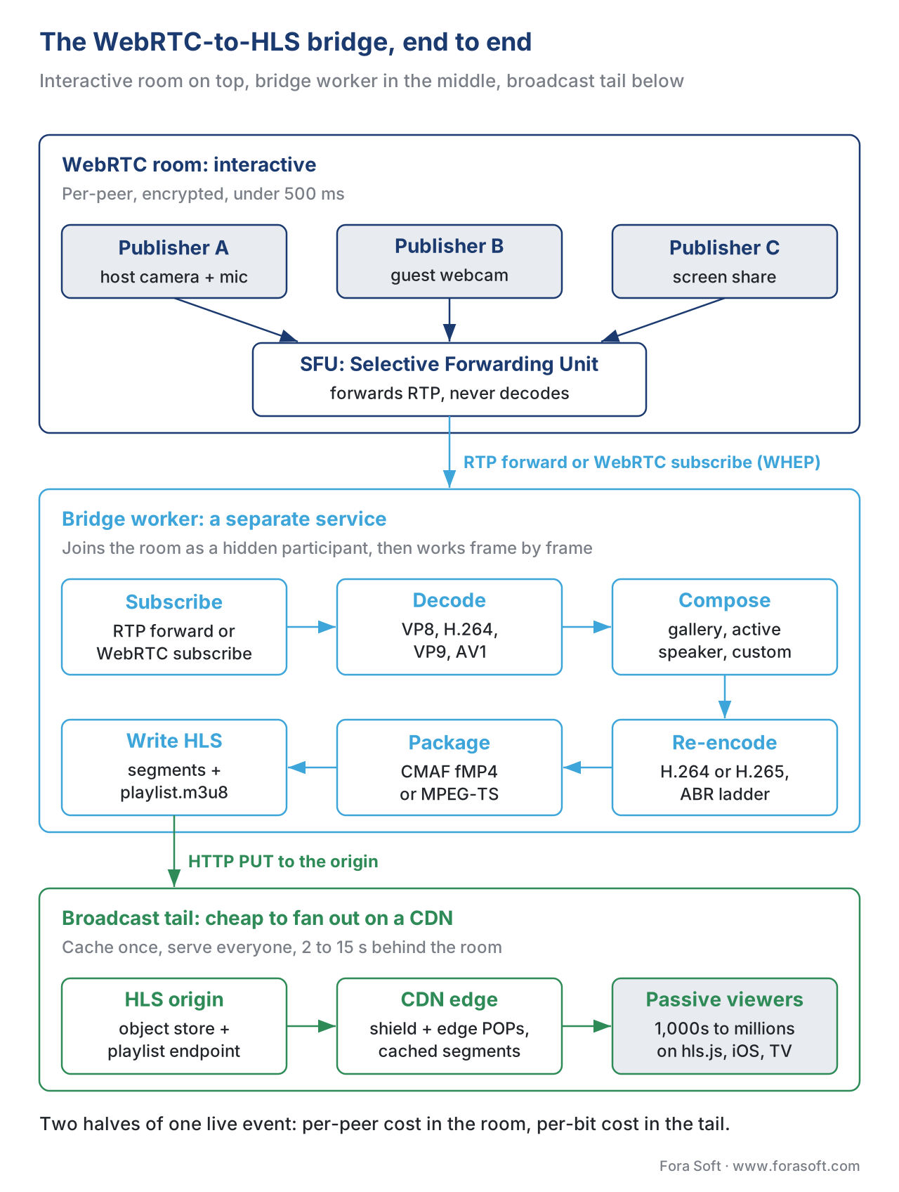 Figure 1. The architectural shape of every WebRTC-to-HLS bridge. The left half is interactive and per-peer-expensive; the right half is broadcast and CDN-cheap; the bridge in the middle does the protocol, packaging, and (usually) the composition work that makes the two halves possible.
Why the SFU does not just do this for you
The reasonable first question is "why is there a separate service at all — can the SFU not just write HLS segments?" The answer comes from how an SFU is built and what it is optimised for. A modern SFU is a high-performance RTP forwarder. It receives encrypted RTP packets, inspects packet headers and a small number of payload-format fields (for layer membership in simulcast and SVC; see Simulcast and SVC), decides which packets to forward to which subscribers, and writes encrypted packets out. It deliberately does not decode the media, because decoding is expensive and the SFU's whole value proposition is that one process can handle hundreds or thousands of participants on commodity hardware. HLS, by contrast, requires that you have decoded frames in hand, because composition (drawing the gallery layout), re-encoding (producing a CMAF-compliant H.264, H.265, or AV1 bitstream at the target rendition ladder), and packaging (writing fMP4 or MPEG-TS segments per the HLS spec) all operate on frames, not on packets.
The LiveKit team made the trade-off explicit in their Universal Egress launch post: "The overriding design goal of the egress system was to keep load off the SFU. Under no circumstances could we impact real-time audio and video performance or quality." Every production-grade SFU — mediasoup, Janus, LiveKit, Jitsi Videobridge, Pion (see SFU comparison) — has reached the same conclusion. The bridge is a separate worker process, often on a separate machine, often horizontally autoscaled, and it talks to the SFU through one of two interfaces: a plain RTP forward of selected tracks, or a server-side WebRTC subscription that lets the bridge appear in the room as a hidden participant.
This is the reason the patterns below all involve a second service. The SFU stays a forwarder; the bridge does the heavy work. The two are operationally independent.
Pattern 1 — Track recording: the minimum-viable bridge
The simplest bridge writes one file per track per participant — no composition, no live distribution, no HLS at all in the first pass. The SFU is asked to forward selected RTP streams to a recorder process over plain RTP, the recorder writes the raw RTP packets to a per-track file in a format like the Meetecho-defined .mjr (the Janus media-jr container), the file is closed when the participant leaves, and a post-processing job converts the per-track recordings into a viewable format — .webm for video, .opus or .m4a for audio — at some point after the room ends. If the product also needs a broadcast HLS stream, the post-processed file is fed into FFmpeg or GStreamer to produce an HLS playlist and segments, which can be uploaded to S3 or any HTTP origin for VOD playback.
Janus has shipped this pattern since its RecordPlay plugin was released; the plugin records to .mjr, the janus-pp-rec tool converts to .webm / .opus, and any downstream pipeline can produce HLS from there. mediasoup's recording demos use the same shape — the SFU calls transport.consume() for the track to be recorded, the consumed RTP is forwarded to a separate process over UDP, and FFmpeg or GStreamer on the other end writes the file. The Kurento mediasoup-demos recording example documents the SDP exchange and the FFmpeg command in detail.
The strength of this pattern is operational simplicity: the recording path is a one-shot RTP forwarder, the recorder writes files, the post-processor runs after the room ends. There are no live transcoding deadlines, no HLS publish loop to keep alive, no composition logic to maintain. The cost is that the output is per-track — one file per camera, one file per microphone — so reconstructing a single playable "video of the meeting" requires a layout decision and a composition pass after the fact. The post-processing is often slow: a 60-minute meeting can take five to twenty minutes to compose and re-encode depending on the layout and the codec target. For products where the recording is delivered minutes-to-hours later as a downloadable file (training-session archives, telemedicine compliance copies, depositions), this is fine. For products where the recording needs to be live-broadcast at near-room latency, it is not.
Real numbers for Pattern 1
A 720p VP8 video track at 1,500 kbps and a 64 kbps Opus audio track produce roughly 175 MB of .mjr per hour per participant. Post-processing an eight-participant room into a 720p gallery layout on a 16-core encode worker with FFmpeg's libx264 in "veryfast" preset takes 18–25 minutes for a 60-minute recording. The cost line is the post-processor's wall-clock time × hourly rate; the storage line is the per-track files plus the composed output.
Pattern 2 — Server-side composition: one bridge worker per room
The second pattern moves composition inside the bridge worker but keeps the worker decoupled from the browser. The bridge subscribes to the SFU as a server-side WebRTC participant (or receives RTP forwards for the selected tracks), runs a media pipeline that decodes each subscribed track, lays the decoded frames into a single composite frame using a layout function the operator picks, re-encodes the composite as a single H.264 or H.265 stream, packages the encoded stream as fragmented MP4 (CMAF) or MPEG-TS, writes segments and the playlist to an HLS origin, and updates the playlist live as new segments close. The pipeline is typically built with GStreamer or FFmpeg's libavfilter graph; the layout function is a few hundred lines of code that places N video sources into a grid, an active-speaker view, a presenter-plus-thumbnails view, or any other arrangement the product needs.
This is the pattern most production bridges actually use under the hood. mediasoup deployments commonly stand up a separate Node or Python worker that runs consume() against the room's tracks, hands the RTP to GStreamer's webrtcbin or rtpbin and a compositor element, and pushes the composed output through x264enc and hlssink2. The GStreamer documentation for hlssink2 describes the element and its low-latency property; turning on low-latency=true enables CMAF chunked transfer for LL-HLS compatibility. Janus deployments do something analogous with the Streaming and VideoRoom plugins plus an external composer.
The latency from speaker to broadcast viewer for a well-tuned Pattern 2 bridge is roughly the sum of: RTP forward inside the data centre (sub-10 ms), decode (one frame, ~33 ms at 30 fps), composite (one frame, sub-10 ms), encode at zero-latency tuning (one frame, ~33 ms), packager segmenting and writing (one part, ~200 ms for an LL-HLS part), CDN propagation (typically 200–500 ms for a first hit through the origin shield; see Origin shielding and tiered caching), and the player's required buffer (1–3 parts for LL-HLS, so 200–600 ms). The total lands in the 2–5 second range for LL-HLS; about 8–15 seconds for classic HLS with 6-second segments and a 3-segment player buffer. The room participants continue to see each other in 200–500 ms; the broadcast tail is 2–5 seconds behind for low-latency, 8–15 seconds behind for classic. (See Latency, glass-to-glass, end-to-end.)
The strength of this pattern is the latency floor — you can ship a true low-latency broadcast tail without renting a third-party SaaS. The cost is operational: the bridge worker is a stateful real-time process that must stay alive for the duration of the room, the layout code lives inside that process and must be maintained, the encoder needs hardware acceleration to scale economically (otherwise CPU dominates), and the segmenter must keep up with wall-clock or the playlist falls behind.
Common mistake: assuming GStreamer's WebRTC support replaces the SFU
A recurring misconception is that GStreamer's webrtcbin element can simply be pointed at the LiveKit or mediasoup room and the bridge is done. It cannot. webrtcbin is a peer-side element; it negotiates a 1:1 PeerConnection with one other peer, not with an SFU's signalling protocol. The bridge must speak the SFU's room protocol on the control plane — RoomService.JoinRoom for LiveKit, the WebSocket signalling for mediasoup, the Janus VideoRoom plugin's API for Janus — and route only the resulting RTP into the GStreamer pipeline once the SFU consents and the SRTP keys are established. This is why every production bridge has a thin SFU-specific shim in front of the GStreamer/FFmpeg pipeline, never a pipeline alone.
 Figure 2. The five production bridge patterns in 2026. Pattern complexity rises left-to-right; operator control over the layout rises with complexity until Pattern 5, where layout is contractually fixed by the vendor.
Pattern 3 — Headless-browser composition: the layout in HTML
The third pattern is what LiveKit, Daily, and several other commercial WebRTC platforms ship as their default room-composite egress. Instead of writing layout code inside the bridge worker, the operator writes a normal web page in HTML, CSS, and JavaScript that renders the desired room view in a browser. The bridge worker then spins up a real headless Chrome instance, navigates to that page, the page connects to the room via the regular web SDK as a hidden participant, the browser renders the live composite to its canvas, and the worker captures the browser's video output frame-by-frame, encodes it, packages it as HLS, and writes the segments.
The LiveKit Egress documentation calls this the "room composite" mode. The Egress source does exactly what is described above: when the egress service receives a RoomCompositeEgressRequest, it opens a Chrome instance, loads the selected template as a web page, connects the page to the LiveKit room as a hidden participant via JavaScript, and the content area of the browser window is captured, encoded, and wrapped in the output container — HLS, MP4, or RTMP to a downstream service. The encoding is done by GStreamer in the LiveKit Egress worker; GStreamer was chosen over FFmpeg for room composition because FFmpeg's libavfilter was harder to compose programmatically for the team's needs.
The strength of this pattern is unbeatable layout flexibility: the operator can ship any view that a web page can render. Active speaker plus four thumbnails, presenter-plus-side-chat, a custom branded overlay with the company logo and a lower-third caption, an animated transition when the active speaker changes — every one of these is a CSS or JavaScript change in the template, not a code change in the bridge worker. The cost is the resource footprint: a headless Chrome instance per active room consumes 1–2 GB of memory and one to two CPU cores even before encoding, so the per-room cost is higher than Pattern 2's bare GStreamer pipeline. For rooms that need bespoke layouts at moderate scale (the typical SaaS conferencing or webinar product), the trade-off is usually right. For rooms with the same fixed layout at very large scale (a sports-betting product with 10,000 live events), Pattern 2 is cheaper.
Real numbers for Pattern 3
A LiveKit-style room-composite egress running headless Chrome at 1280×720 / 30 fps with x264enc at zero-latency tuning and LL-HLS output sits at roughly 1.6 GB RAM and 1.8 CPU cores per active room on a modern Intel Xeon. The end-to-end latency from active speaker to LL-HLS viewer is in the 3–5 second range for an LL-HLS configuration with 200 ms parts, and 8–15 seconds for classic HLS with 4–6 second segments. The LiveKit team explicitly notes that RTMP relay from LiveKit Egress carries a built-in 1–2 second buffer on top of LL-HLS latency for the relay's reliability — meaning a WebRTC → LiveKit Egress → RTMP → downstream-HLS path adds that buffer on top of the bridge's own latency, often pushing total glass-to-glass past 6 seconds.
Pattern 4 — WebRTC-to-RTMP egress feeding a separate live encoder
The fourth pattern pushes the HLS packaging out of the bridge worker entirely and delegates it to an existing live-encoder service — AWS Elemental MediaLive, Wowza Streaming Engine, NimbleStreamer, an Ant Media Server installation, Mux Video, Cloudflare Stream Live, or Amazon IVS. The bridge worker still does the WebRTC subscription and the composition; it then re-encodes the composite, wraps the encoded stream in RTMP, and pushes the RTMP stream to the downstream live encoder, which does the ABR ladder (see Building a bitrate ladder), the CMAF packaging, the HLS and DASH playlist generation, the SCTE-35 ad-marker insertion, and the CDN integration. The bridge worker's job ends at "publish a single high-bitrate RTMP stream to the configured endpoint".
This is the dominant pattern for any product that already runs a video infrastructure for non-WebRTC content and wants to add an interactive WebRTC origin to it. Amazon Chime SDK ships exactly this pattern as its Live Connector feature, which captures a Chime meeting and pushes RTMPS to Amazon IVS or AWS Elemental MediaLive — the downstream service does the HLS work. Dolby OptiView (the rebranded Millicast) supports RTMP / RTMPS ingest that is transmuxed to WebRTC for low-latency egress and can be teed off to HLS through a separate downstream service. The pattern works for any combination of WebRTC SFU and live encoder so long as the bridge worker can be configured to push RTMP to an arbitrary URL.
The strength is operational sanity: a team that already runs a live-encoder cluster does not need to learn a second packager. The cost is latency: every RTMP hop adds buffering on both sides (the publisher's RTMP sender, the receiver's RTMP ingester), the live encoder adds its own segmenting latency, and the HLS player adds its own buffer. A 6–12 second glass-to-glass figure is realistic; sub-5 second is hard.
Why RTMP, in 2026, when the protocol is otherwise dying
RTMP is the lingua franca of live-encoder ingest (see RTMP in 2026: dead protocol, undying default). Every live encoder built in the last 15 years accepts RTMP, and the protocol's combination of TCP delivery, predictable framing, and ubiquitous server-side parsers makes it the path of least resistance between a custom bridge and any commercial packager. SRT (see SRT deep dive) is the modern alternative for public-internet hops, and a small number of bridges support pushing SRT instead of RTMP — but inside a data centre, RTMP is fast enough and supported everywhere. The bridge does not care that RTMP is dying for end-to-end delivery; it uses it as a local interconnect between two services, and on that segment RTMP's age is not a liability.
Pattern 5 — Managed commercial bridges
The fifth pattern is buying the bridge as a SaaS. The vendors that ship a true end-to-end WebRTC-to-HLS bridge in 2026 are LiveKit Cloud (Universal Egress, with HLS or MP4 output and RTMP relay), Dolby OptiView (the Millicast platform with WHEP delivery and HLS egress through partner integrations), Amazon Chime SDK Live Connector, Cloudflare Stream (with the caveat noted below), 100ms, Vonage Video API, Daily, Twilio Programmable Video, and a small number of broadcast-grade specialists like Norsk and Phenix. The operator implements WebRTC on the platform side and signs a contract that includes a bridge to HLS or DASH on the egress side. The vendor handles everything described in Patterns 2, 3, and 4 invisibly.
The trade-off is the standard managed-service trade: the operator gets to ship the feature in a quarter instead of a year, the per-minute cost is higher than a self-built bridge running on owned hardware, the layout flexibility is whatever the vendor's templates expose (LiveKit's room composite is template-defined HTML; Daily's is one of a handful of fixed presets), and the vendor's roadmap controls when new features arrive. Most products that ship a bridge as part of their first conferencing release start here; some migrate to Pattern 2 or 3 once volume justifies the engineering work to internalise the bridge.
The Cloudflare Stream caveat
Cloudflare Stream supports WebRTC ingest and egress through WHIP and WHEP (see WHIP: WebRTC ingest, RFC 9725 and WHEP: HTTP-based egress for WebRTC). As of mid-2026, the platform's own WebRTC documentation explicitly states that WHIP and WHEP must be used together — you cannot publish via WHIP and play back via HLS or DASH on the same Cloudflare Stream entry. To produce an HLS broadcast from a Cloudflare-hosted WebRTC stream, the operator's bridge worker must subscribe via WHEP, re-encode, and push RTMP (or use Cloudflare's Live RTMP ingest path) to a Cloudflare Stream Live input that then produces HLS. The path works; it is just not a one-step "WHIP-in, HLS-out" call on Cloudflare's API. Other vendors (LiveKit, Mux, AWS) collapse the two halves into a single managed pipeline; this is one of the reasons LiveKit Cloud has captured a disproportionate share of the WebRTC-bridge-to-HLS market in 2025–26.
Choosing a pattern — the decision tree that actually fits production
The honest decision tree starts from three questions, in order.
- Are the broadcast viewers a feature or a side effect? If the product's primary mode is conferencing or telemedicine and the recording is a compliance copy that no live audience ever watches, Pattern 1 — track recording with offline post-processing — is the right answer. The bridge is a one-shot batch job. Nothing complex needs to keep running in real time.
- If broadcast viewers are a feature, are they hundreds or many thousands? For hundreds of viewers, the operator usually has the bandwidth budget for direct WebRTC delivery to the tail (Pattern 5's WHEP variant, or a self-hosted WebRTC egress) and an HLS path is optional. For many thousands, HLS becomes mandatory because the WebRTC cost line is steep — and the bridge has to be a real-time pipeline, which forces Pattern 2, 3, 4, or 5.
- Does the product need a bespoke layout, or is one of three or four standard layouts enough? Bespoke layout (custom branding, custom overlays, custom transitions) usually means Pattern 3 (headless browser, HTML/CSS templates) — the layout work is in HTML rather than in a media pipeline, and that is the cheapest place to maintain it. Standard layouts at very high scale push toward Pattern 2 (GStreamer pipeline with compositor element), which is much cheaper per-room but inflexible. Standard layouts at moderate scale that the team does not want to maintain are the obvious case for Pattern 5 (managed bridge).
A worked example, with arithmetic. Suppose the product is a B2C live-shopping platform. The room has one host on WebRTC; the broadcast tail is 30,000 viewers on HLS. Each viewer watches 720p at 2,500 kbps for 45 minutes of show. Direct WebRTC delivery to 30,000 viewers at 2.5 Mbps each would consume 75 Gbps of egress for the entire show, billed per gigabyte — at $0.005/GB CDN egress, that is 75 Gbps × 2,700 s ÷ 8 = 25,312 GB × $0.005 = $126 per show, but only because the WebRTC server farm could even reach 75 Gbps, which assumes a substantial WebRTC distribution layer (cascading SFUs and regional bridges; see WebRTC at scale). HLS delivery of the same content through a multi-CDN setup (see Multi-CDN architecture) consumes the same 25,312 GB but the per-GB CDN price for cacheable HLS segments at this volume is in the $0.002–$0.003 range — call it $63 per show. The bridge's CPU and packaging cost is a fixed addition (Pattern 2 or 3 at $1–$3 per room-hour) that is dwarfed by the savings beyond a few thousand viewers. The latency penalty — broadcast viewers are 3–5 seconds behind the host — is fine for shopping; it is not fine for an auction. The choice for the shopping platform is Pattern 2 or Pattern 3 with LL-HLS; the choice for the auction is Pattern 5 with WHEP and no HLS hop at all.
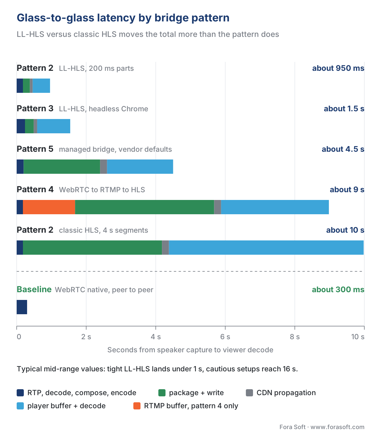 Figure 3. Glass-to-glass latency budget for each bridge pattern, broken into the seven stages that add measurable delay. Pattern 1 is omitted because it produces a file rather than a live stream; the four live patterns all land in the 2–15 second range, with the choice of LL-HLS vs classic HLS dominating the total more than the choice of pattern.
What ships in production, by SFU
The five major open-source SFUs each have an idiomatic bridge story in 2026.
LiveKit ships Egress as a separate worker binary that handles all four live patterns (Patterns 2, 3, 4, and the "Pattern 5" version when run inside LiveKit Cloud). Egress is the most opinionated of the five: room composition is HTML-template-based, encoding is GStreamer, HLS output is via hlssink with optional LL-HLS parts, RTMP output is for downstream live encoders or directly to Twitch/YouTube. The community has standardised around it.
mediasoup does not ship a bridge as part of the core library. The pattern is to write a separate worker in Node or Python that calls transport.consume() for the tracks to be recorded, forwards the resulting RTP to a GStreamer or FFmpeg process via plain RTP, and lets that process do the composition, encoding, and packaging. The mediasoup community maintains several reference implementations of this pattern, most notably the mediasoup3-record-demo and the Kurento mediasoup-demos recording example. Production deployments often pair this with an internal layout service the company maintains.
Janus ships the RecordPlay plugin for per-track recording into .mjr files, and the Streaming plugin for re-broadcast. Several Janus deployments add a custom plugin or external process to do the HLS work; the Meetecho team's documentation describes the recording mechanism in detail and janus-pp-rec is the official post-processor.
Jitsi Videobridge uses Jibri (Jitsi Broadcasting Infrastructure) for the bridge work. Jibri is essentially Pattern 3 — a headless Chrome instance that joins the meeting as a hidden participant, captures the screen, and either records to MP4 for archive or pushes RTMP to a downstream service (typically YouTube Live for the Jitsi Meet community deployment). Jibri does not produce HLS directly; the HLS step is handled downstream.
Pion is a Go library rather than an opinionated server, and bridges built on Pion are typically custom — the team writes the room subscription, the composition (often using Go bindings to GStreamer via go-gst, as LiveKit does), and the encoding-and-packaging path. Twitch and several other large WebRTC deployments use Pion in production with custom bridge stacks.
Pitfall: the WebRTC bandwidth estimator and the bridge's silent throttling
A subtle failure mode that catches every team at least once is the interaction between the SFU's bandwidth estimator (see WebRTC bandwidth estimation) and the bridge worker. The bridge subscribes to the room as if it were a real participant, which means the SFU treats it as a real subscriber and applies its normal congestion-control logic — Google Congestion Control or transport-cc — to the stream it forwards to the bridge. If the bridge's link to the SFU briefly experiences packet loss (a noisy intra-DC link, a TURN relay congesting under load), the SFU downgrades the simulcast layer or the SVC layer it forwards to the bridge, and the bridge's HLS output silently drops resolution. The room participants on healthy links continue to see high-resolution video; the broadcast tail sees a 360p stream that the host never sent at 360p.
The fix is to subscribe the bridge to the highest available layer explicitly and pin it there, treating the bridge as a "VIP subscriber" the SFU never downgrades. LiveKit Egress, Jibri, and most production bridges do this by default; rolling your own Pattern 2 bridge requires explicitly setting the preferred layer at subscription time and disabling layer-downgrade for that subscriber. The SFUs all expose the knob; the failure mode is forgetting to use it.
A worked numerical example: latency budget for an LL-HLS bridge
Suppose a live-shopping product runs Pattern 2 with LL-HLS output. The host publishes 1080p H.264 at 4 Mbps; the bridge is on the same data centre as the SFU; the LL-HLS configuration uses 200 ms parts and a 6-second segment target; the target player buffer is two parts.
Stage-by-stage:
- Speaker's microphone-to-encoder capture: 30 ms.
- Speaker's H.264 encoder pacing (libwebrtc default): 30 ms.
- RTP transit from speaker to SFU over the public internet: 40 ms.
- SFU forwarding the RTP packet to the bridge subscriber (intra-DC, sub-millisecond network plus SFU's pacing): 5 ms.
- Bridge decoder (one frame at 30 fps): 33 ms.
- Compositor (one frame): 8 ms.
- Bridge encoder at zero-latency tuning (one frame): 33 ms.
- Packager closing a 200 ms part and writing it to the origin: 200 ms.
- HTTP propagation from origin to CDN edge: 80 ms.
- Player's preload-hint fetch and buffer of two parts: 400 ms.
Sum: 30 + 30 + 40 + 5 + 33 + 8 + 33 + 200 + 80 + 400 = 859 ms from capture to first-byte-decodable at the viewer, plus the viewer's own decoder pacing and one-frame display: roughly 100 ms more. Total glass-to-glass is in the 950 ms to 1.1 second range when the configuration is tight and the player implementation is good (hls.js with LL-HLS support; see hls.js deep dive). Doubling the player buffer to four parts (typical for stability) pushes the total to 1.4–1.6 seconds. A classic-HLS configuration with 4-second segments and a 3-segment player buffer pushes the total to 14–16 seconds, which is fine for a product where chat is the primary interactivity and the host can naturally pause for the broadcast tail.
The point of writing the budget out: every stage has a number. The bridge is not magic; it is the sum of well-known stage latencies, and every one of them is tunable inside the limits of the spec.
Comparison table — five patterns side by side
| Pattern | Composition location | Live or batch | Typical glass-to-glass | Bespoke layouts | Per-room cost (relative) | Operator complexity |
|---|---|---|---|---|---|---|
| 1. Track recording | None (per-track files) | Batch (post-process) | N/A — file delivered later | None (post-comp) | Low | Low |
| 2. Server-side compositor | Bridge worker (GStreamer) | Live | 2–5 s LL-HLS, 8–15 s classic | Limited (code change) | Low | High |
| 3. Headless browser | Bridge worker (HTML/CSS) | Live | 3–5 s LL-HLS, 8–15 s classic | Unlimited | Medium | Medium |
| 4. RTMP to live encoder | Bridge + downstream encoder | Live | 6–12 s typical | Limited (bridge side) | Low at bridge; encoder billed separately | Medium (two services) |
| 5. Managed bridge SaaS | Vendor | Live | 3–8 s typical | Vendor templates | Highest per minute | Lowest |
Where Fora Soft fits in
Fora Soft has shipped WebRTC products since 2008 and WebRTC-to-HLS bridges in production across video conferencing, telemedicine, e-learning, and live-shopping verticals. Telemedicine deployments commonly need Pattern 1 — a compliance copy of every visit, archived to S3, never broadcast live — and the engineering work is mostly around regulatory metadata (timestamps, participant IDs, retention policy). E-learning and live-shopping deployments more often need Pattern 2 or Pattern 3 — a low-latency public HLS feed that lets a much larger passive audience join the session — and the engineering work is dominated by the layout templates, the encoder tuning for the target rendition ladder, and the operational discipline of running a stateful bridge fleet that autoscales with active rooms. The lesson from these projects: the bridge is rarely the part of the product the customer sees, but it is reliably the part that determines whether the launch scales beyond a few hundred concurrent viewers. Our WebRTC developers build these bridges on mediasoup, LiveKit and Janus, and for products already on LiveKit our LiveKit development team wires recording and HLS broadcast into the same rooms.
The book
Video Streaming: A Complete Guide to Video Delivery: From ABR and CDNs to Players, WebRTC, DRM, and the Economics of Streaming
Book 3 covers both sides of the bridge: how the SFU forwards and subscribes, how a WebRTC room and an HLS audience share one event, and what each viewer costs on a media server versus a CDN. Book 2 goes deep on the tail, from CMAF packaging to LL-HLS parts and preload hints. Written by Nikolay Sapunov, CEO at Fora Soft.
Need to record your WebRTC rooms or stream them to a larger audience?
Tell us your SFU, the layout you need and the latency your viewers will accept. We will pick the bridge pattern, size the worker fleet and estimate the cost per room, from compliance recording to a live LL-HLS feed. 250+ video products shipped since 2005.
See our case studies
Case study
VALT
HIPAA-compliant video recording and observation for 770+ U.S. organizations and 50,000+ users, with RTMPS streaming, HLS playback and word search inside recordings.
Case study
Sprii
Live shopping with WebRTC and RTMP multistreaming to web stores, Facebook and Instagram: 88,600 campaigns and 12.3 million products sold in 2024.
Case study
BrainCert
WebRTC virtual classrooms: 500M+ real-time classroom minutes across 10 data centres with 99.995% guaranteed uptime.
What to read next
WebRTC
WebRTC Delivery: From Peer-to-Peer to Scaled Distribution
Cascading SFUs for the front row, a bridge to LL-HLS for everyone else.
Low latency
LL-HLS in Depth: Parts, Preload Hints, Blocking Reload, Rendition Reports
The output format behind the sub-2-second bridge budgets.
Architecture
The “Switching Protocols” Reality: Hybrid Stacks
Running WebRTC and HLS side by side from one ingest.
Protocols
RTMP for Distribution and Why It's Truly Dying
Why RTMP survives as the hand-off in pattern 4, and nowhere else.
References
- RFC 8216 — HTTP Live Streaming, IETF, August 2017. Base HLS specification; LL-HLS extensions are tracked in
draft-pantos-hls-rfc8216bis-22(current as of early 2026, subject to update). - Apple HLS Authoring Specification for Apple Devices, Apple, revision 2025-09. Normative source for LL-HLS production requirements on the Apple ecosystem; supersedes vendor blog posts that pre-date the 2023 removal of HTTP/2 server push from the spec.
- W3C WebRTC 1.0 Recommendation, W3C, March 2023. Browser API for
RTCPeerConnectionandRTCRtpSender; the contract every bridge subscriber relies on. - RFC 8853 — Using Simulcast in SDP and RTP Sessions, IETF, January 2021. Cited because the bridge's subscription is a normal simulcast subscription, with all the same RTP-stream-identification mechanics.
- RFC 9725 — WHIP: WebRTC HTTP Ingestion Protocol, IETF, March 2025. WHIP-side ingest path some bridge deployments rely on to take RTMP-style encoders into the WebRTC plane.
- LiveKit Egress — Source repository, LiveKit, 2026. Reference implementation of Patterns 2, 3, and 4 in a single Go binary; the most-deployed open-source bridge in production.
- LiveKit Egress overview — official documentation, LiveKit, accessed 2026-05-25. Defines room composite, track, track composite, and web egress modes; the latency budgets for each path.
- LiveKit Universal Egress launch announcement, LiveKit, 2023. The design constraint that the SFU must never be slowed by the bridge — quoted in the article body.
- Janus RecordPlay plugin documentation, Meetecho, accessed 2026-05-25. The Janus per-track recording mechanism in
.mjrformat and thejanus-pp-recpost-processor. - Kurento mediasoup-demos recording example, Kurento, accessed 2026-05-25. Reference SDP and FFmpeg command for forwarding mediasoup RTP to an external recorder.
- mediasoup3 record demo, Ethand, accessed 2026-05-25. GStreamer-based recording pipeline for mediasoup v3.
- GStreamer hlssink2 element documentation, GStreamer Project, accessed 2026-05-25. The element most Pattern 2 bridges use to write HLS segments and the low-latency mode that enables CMAF chunked transfer.
- Amazon Chime SDK launches Live Connector for streaming, AWS, accessed 2026-05-25. Pattern 4 / Pattern 5 reference: Chime → RTMPS → IVS or MediaLive → HLS.
- Cloudflare Stream WebRTC documentation, Cloudflare, accessed 2026-05-25. The "WHIP and WHEP must be used together" constraint that shapes the Cloudflare-specific bridge path.
- Dolby OptiView RTMP / RTMPS ingest documentation, Dolby OptiView, accessed 2026-05-25. Dolby's Pattern 4 ingest path used by bridges that want WebRTC-to-RTMP plus low-latency WebRTC egress.
