


Why this matters
If you are a product manager, founder, or operations lead at a company shipping conferencing, telemedicine, e-learning, live shopping, contact-centre video, or an AI-agent product, the difference between a system that survives the moment your traffic doubles and a system that goes dark is almost entirely an architectural decision made long before the traffic arrives. A confident buyer should be able to answer three questions without flinching: how many concurrent participants the system supports before it adds a server, how the system behaves when one of those servers fails, and what changes when AI agents enter the room as first-class participants. This article answers those three questions for the non-network-engineer, points the senior engineer at the right code paths and references, and gives a working mental model of every meaningful scaling pattern in WebRTC as it stands in 2026.
Where a single SFU stops scaling
A Selective Forwarding Unit is the box in the middle of a multi-party WebRTC call that receives every participant's media, decides which streams to send to which other participants, and forwards them. For the wider topology picture — Mesh, MCU, SFU — see SFU vs MCU vs Mesh: the three WebRTC topologies.
A single SFU is a single process on a single machine. Its limits are physical, and they show up in this order as load grows:
The first ceiling is CPU. Even though an SFU does not transcode, it parses RTP headers on every incoming packet, runs SRTP encryption on every outgoing packet, runs RTCP feedback loops, and handles ICE consent freshness for every peer connection. A modern x86 server with 32 cores and AES-NI hardware can comfortably forward perhaps 600 to 1,200 video streams at 1 Mbps before the cores saturate. Mediasoup, the C++/Node.js SFU, is widely reported to land at roughly 500 to 800 concurrent video participants per node in a well-tuned production deployment; LiveKit's Go-based SFU is in the same range; Janus's C engine pushes higher with careful tuning. The numbers move with the codec, the simulcast layer count, and the call shape, but the order of magnitude is the same.
The second ceiling is network. A 10 Gbps NIC at 80% utilisation moves 1 GB/s of media. A 1 Mbps video stream consumes about 125 KB/s of egress per subscriber. A 100-participant call where every participant subscribes to every other publisher is 100 × 99 ≈ 9,900 streams of egress per second on the SFU — at 1 Mbps each that's 9.9 Gbps, which saturates a 10 Gbps link. The pattern is brutal: egress scales as O(N²) for fully-meshed conferences, because each of N participants subscribes to N−1 others. LastN forwarding (covered below) breaks the quadratic; without it, the network card is the wall.
The third ceiling is operational. A single SFU is a single point of failure. If the process crashes, every active call drops. If the host has a kernel panic, every active call drops. If the cloud provider has a regional outage, every active call drops. Beyond a few hundred users, no production team accepts that risk.
The single-SFU architecture is the right answer for a tutorial, an MVP, and any product whose peak concurrent call size is under a few hundred. Past that, the architecture has to change.
 Figure 1. Why one SFU runs out of room. CPU saturates first in dense conferences with high publisher-to-subscriber fan-out; network saturates first in star-shaped broadcasts; operational risk caps any production deployment at a single-box scale.
Cascaded SFUs: the standard scaling pattern in 2026
A cascaded SFU architecture replaces the single media server with a mesh of media servers that forward each other's traffic. A participant connects to the SFU closest to them — geographically, by latency, or by load — and that SFU forwards the participant's media to the other SFUs that hold subscribers in the same room. From the user's point of view, a cascaded system looks exactly like a single SFU; from the system's point of view, the load is now distributed across as many nodes as the operator wants to pay for.
The pattern is sometimes called regional bridging when the nodes are placed in geographically distinct data centres and the inter-node traffic rides the cloud provider's backbone rather than the public internet. The result: a participant in Tokyo connects to a Tokyo SFU, a participant in Frankfurt connects to a Frankfurt SFU, and the two SFUs exchange media over the cloud's private backbone — which is faster, more predictable, and almost always cheaper than two public-internet RTT hops between Tokyo and Frankfurt browsers.
LiveKit calls this architecture a distributed mesh and runs it as the default for its cloud product; Jitsi Videobridge calls it Octo and ships it inside Jitsi Meet for any conference that crosses a configurable participant threshold; mediasoup exposes the primitive as Pipe Transports, which join two SFU instances at the API level and let the application build the cascade explicitly; Janus uses its VideoRoom plugin with multistream forwarding for the same effect. Twilio Video, before its 2024 sunset, ran a cascaded architecture; Daily.co's SFU runs a cascade; Cloudflare's Realtime SFU is built on a cascade by definition because Cloudflare's edge is intrinsically distributed. By 2026, every production-grade SFU offers cascading, either as a built-in feature or as a primitive the application composes.
How the cascade actually works
Three things have to be right for a cascade to deliver the latency and reliability properties the architecture promises.
The first is room-to-node routing: when a new participant joins a room, the system has to decide which node they connect to. The two common strategies are participant locality (the node closest to the participant) and room affinity (the node that already holds the most participants in this room). In practice production systems combine the two: prefer the node closest to the new participant unless joining that node forces an extra cascade hop that a different node would avoid. LiveKit's router uses Redis as a coordination layer; Jitsi's Octo uses a central bridge selector; mediasoup leaves the choice to the application's signalling layer.
The second is inter-node transport: how SFU A forwards a participant's media to SFU B. Mediasoup's Pipe Transport uses plain RTP over UDP over the same data-centre network the SFUs share; LiveKit uses an internal QUIC-based protocol; Jitsi's Octo uses a custom UDP relay. The shared idea is that the inter-node hop is not a regular WebRTC peer connection — there is no DTLS handshake per stream, no ICE, no SRTP rekeying — because both ends are inside a trusted network and the overhead of a full DTLS-SRTP exchange per stream would be ruinous at cascade scale. Authentication between nodes is done once, at boot, typically with mutual TLS or a shared HMAC key.
The third is session integrity: when a participant in Tokyo joins a room that already has a participant in Frankfurt, the Tokyo SFU must learn about the Frankfurt participant, and vice versa, in time for the new participant to subscribe. This is a distributed-state problem the coordination layer solves; Redis, etcd, and Apache ZooKeeper are the typical choices. Production systems run sub-second propagation: the new participant sees the existing roster within 50 to 200 ms of joining.
 Figure 2. A cascaded SFU mesh. Three regional nodes share a room; each participant connects to the nearest node; node-to-node hops ride the cloud backbone, not the public internet; a coordination layer (Redis here) keeps the room roster synchronised across the mesh.
What cascading is not
Cascading is not the same as federation — separate WebRTC platforms exchanging media across organisational trust boundaries (the IETF rtcweb working group has explored federation, but it remains rare in production). A cascade is a single platform running a single room across multiple physical locations.
Cascading is not the same as horizontal scaling of the signalling layer — adding more web servers in front of the SFU. Signalling does scale horizontally trivially (it is stateless HTTP plus a WebSocket), and every serious WebRTC product scales signalling separately from media. But the media plane needs the cascade pattern; load-balancing signalling alone does not increase media capacity.
And cascading is not the same as multi-region failover. A cascade is active-active: every region carries live traffic. Failover is a separate property the cascade gives you almost for free, because losing one region degrades the call (participants in that region reconnect to the next-nearest node) rather than killing it.
LastN and dominant-speaker forwarding: making the network reasonable
Even with a cascade, the network bill at a 100-participant call is unreasonable if every subscriber receives every other publisher's video. LastN is the optimisation that almost every modern SFU implements: only the N most recently-active speakers' video streams are forwarded to any given subscriber. The other participants' audio is still mixed in (audio is cheap); only the video forwarding is constrained.
The dominant-speaker identification algorithm Jitsi published in 2015 (Politis, Tsioutas, Mavridis — "Last N: Relevance-Based Selectivity for Forwarding Video in Multimedia Conferences") is the de-facto reference: it works on the RTP audio-level extension header (RFC 6464) without decoding the audio, ranks endpoints by recent voice activity, and the SFU forwards only the top N video streams to each subscriber. Jitsi's measurements at the time: a SFU using LastN with N=10 used 45% less CPU and 63% less bandwidth than the same SFU forwarding all streams. The numbers are an order-of-magnitude lower today on faster hardware, but the ratio holds: LastN turns an O(N²) network bill into an O(N) network bill, which is the difference between a call that survives 100 participants and a call that survives 1,000.
In a cascaded mesh, LastN runs per-node: each regional SFU computes the dominant speakers across the room (using the same audio-level signal it receives from every other node in the mesh) and forwards only those to its local subscribers. The dominant-speaker computation is global; the forwarding decision is local. This is the second reason cascaded SFUs scale: the cascade carries every audio stream between nodes (audio is cheap — Opus at 32 kbps × 100 participants × 3 nodes is under 10 Mbps), but only the dominant N video streams.
Combined with simulcast and SVC (covered in Simulcast and SVC: how the SFU serves a heterogeneous audience), LastN gives the SFU a per-subscriber choice: which spatial layer of which dominant speaker's video to send. A subscriber on a phone gets the low-resolution layer of the active speaker; a subscriber on a desktop in a 4-up grid gets the medium-resolution layer of four speakers. Same SFU, same room, different bills.
Numeric example: scaling a 100-participant conference
Let's compute the cost of scaling a 100-person conference with and without the patterns above.
Naive star topology, one SFU, no LastN. Every participant publishes one 1 Mbps video stream; every participant subscribes to every other publisher's video. SFU egress is 100 × 99 × 1 Mbps = 9.9 Gbps. A single 10 Gbps NIC is saturated; the call cannot reliably scale past about 80 participants on this hardware. Daily peak-hour egress, if the call runs 4 hours a day: 9.9 Gbps × 4 h × 3,600 s × 1 GB / 8 Gb = roughly 17.8 TB/day of egress per call.
Same call, LastN with N=4. Every subscriber receives the four most-recently-active speakers' video plus the mixed audio of everyone else. SFU egress per subscriber: 4 × 1 Mbps + 100 × 32 kbps (audio) = 7.2 Mbps. SFU total egress: 100 × 7.2 Mbps = 720 Mbps. The single 10 Gbps NIC is now at 7% utilisation; the call fits comfortably on one box. Daily egress: roughly 1.3 TB/day — a 14× reduction.
Same call, LastN N=4, cascaded across three regional SFUs (33 participants per region). Each regional SFU forwards: 4 active-speaker videos × 33 local subscribers = 132 video flows locally, plus the 4 active-speaker videos shared between nodes = 4 × 2 inter-node hops = 8 inter-node video flows. Per-region SFU egress: 132 × 1 Mbps + 33 × 100 × 32 kbps = 232 Mbps. Inter-node egress per pair: 4 × 1 Mbps + 67 × 32 kbps audio (the non-local participants' audio) = 6.1 Mbps. The architecture now handles regional failure (one node down degrades but does not drop the call), gives Tokyo participants Tokyo latency, and the per-region per-hour bill is roughly 104 GB — a third of what the single-SFU LastN model carried, distributed across three regions.
The numbers above are illustrative; production rates depend on codec, simulcast layer choice, RTCP feedback overhead, and the specific inter-node protocol. But the order of magnitude is correct, and the pattern is universal: LastN delivers the first 10× of scaling; cascade delivers the second.
The 100K-viewer architecture: SFU-to-HLS broadcast
Cascaded SFUs scale conferences — calls where most participants are also publishers — into the low thousands. But there is a different scale problem on the other side: a town hall, a live-shopping stream, a sports watch-along, where a handful of presenters broadcast to tens or hundreds of thousands of viewers, almost none of whom publish anything. WebRTC is the wrong tool for that audience size, for two reasons:
The first is economics. A 100,000-viewer WebRTC broadcast over a cascaded SFU mesh is 100,000 active peer connections, each with its own DTLS state, ICE consent freshness, RTCP feedback loop, and SRTP context. The CPU and memory bill on the SFU side is hostile, and the egress bill is no better than CDN egress would be. WebRTC has no caching layer; a CDN does.
The second is what the audience actually needs. The presenters care about latency — they want the chat reactions to land while they are still speaking — but the audience mostly cares about reliability, scrub-back, and the ability to join late. Those properties are exactly what HTTP-based streaming was designed for, and what WebRTC was specifically designed not to be.
The 2026 production pattern is the SFU-to-HLS bridge: the SFU continues to handle the publisher side and the small interactive audience (presenters, panellists, VIPs, contact-centre agents — anyone whose latency budget is sub-second), and a packager attached to the SFU repackages the active-speaker mix into a Low-Latency HLS or chunked-CMAF stream that the CDN fans out to the wider audience. The bridge gives the wider audience a 2-to-5-second glass-to-glass latency through LL-HLS — slower than WebRTC's 100–300 ms, but still fast enough that the chat reactions feel live, and orders of magnitude cheaper to serve. The packager appears to the SFU as a regular subscriber: it joins the room, pulls the active-speaker layout, and emits LL-HLS segments to an origin that a CDN like Cloudflare Stream, Fastly, AWS CloudFront, or Akamai then distributes.
This pattern is the architecture LiveKit uses for its livestreaming product (see LiveKit's WebRTC vs HLS post for the 2026 numbers), the same architecture Mux's Real-Time Streaming product exposes, and the architecture the Daily.co Egress feature implements. Cloudflare's Realtime SFU pairs with Cloudflare Stream for the same effect. The pattern is now so standard that newer protocol families — see Media over QUIC — are explicitly designed to make the bridge less seam-y, by treating interactive and broadcast media on the same transport.
The detailed mechanics of the bridge — how the SFU's RTP frames become CMAF segments, how the active-speaker layout is composed, how audio mixing works — are covered in Recording, Broadcasting, and the WebRTC-to-HLS Bridge. For the LL-HLS reader side, see LL-HLS in depth.
 Figure 3. The SFU-to-HLS bridge. The interactive tier runs on cascaded WebRTC and lives inside a 300 ms latency budget. The broadcast tier rides an LL-HLS packager and a CDN and lives inside a 2-to-5 second budget. The two share publishers, not subscribers.
AI agents enter the room
Until 2023, every participant in a WebRTC room was a human with a browser. By 2024 the first generation of AI voice agents — Vapi, Retell, Vocode — joined rooms as headless participants over WebSockets. In 2025 the LiveKit Agents 1.0 framework and Daily's Pipecat 1.0 framework formalised the pattern, and OpenAI shipped the Realtime API, Google shipped the Live API, and Anthropic shipped real-time multi-modal voice — all designed to be wrapped by an agent framework and joined to a WebRTC room as a peer participant. In 2026, an "AI agent participant" is a routine load on top of the same SFU infrastructure that carries human calls.
An AI agent in a WebRTC room is, mechanically, the simplest possible peer. It runs as a process somewhere (typically inside the same data centre as a regional SFU, to minimise hop count), joins a Room as a participant, subscribes to one or more human audio tracks, publishes its own audio track, and runs the voice-agent pipeline internally: voice-activity detection (VAD) to detect end-of-speech, speech-to-text (STT) to transcribe what the human said, a large language model (LLM) to generate a response, and text-to-speech (TTS) to synthesise that response back into audio that flows out over the agent's WebRTC publish track. The agent never sees a video frame in the simplest case; in 2026 it increasingly does, because the GPT-4o-tier "Realtime" APIs accept video and the LLM does basic visual reasoning inside the same turn.
LiveKit Agents 1.5 — the most-deployed framework
LiveKit Agents is open source, runs on Python 3.11+, and is, as of the April 2026 1.5 release, the most-deployed agent framework on top of WebRTC. The architecture has three layers: a Worker registers itself with the LiveKit server, the server dispatches a worker to a Room when a human joins, and the worker runs a VoicePipelineAgent that orchestrates VAD/STT/LLM/TTS via plug-and-swap modules.
The 1.5 release added two features that matter for production: adaptive interruption handling — the agent can be interrupted mid-utterance, the TTS playback halts, the partial transcription is committed to the LLM's context, and the next user turn is processed cleanly — and native Model Context Protocol (MCP) tool support, which lets the agent call external tools (a customer-database lookup, a calendar booking, a payment confirmation) inside the same turn without separate orchestration.
Because LiveKit Agents joins as a normal participant, the cascaded SFU mesh distributes agent traffic the same way it distributes human traffic. A worker fleet runs in every region; a Tokyo human gets a Tokyo agent; latency stays sub-second.
Pipecat 1.0 — the vendor-neutral alternative
Pipecat reached 1.0 on April 14, 2026, maintained by Daily.co and entirely vendor-neutral. Pipecat is pipeline-first: you declare a directed graph of processors — VAD, STT, LLM, TTS, business logic — and audio frames flow through them. The model is more flexible than LiveKit Agents and the deployment story is more varied: Pipecat workers can speak WebRTC (via Daily's SDK or any WebRTC transport adapter), SIP (for telephony), WebSockets, or even MQTT for embedded scenarios. The trade-off is that Pipecat does not give you a media server — you bring your own — where LiveKit Agents and LiveKit's SFU are designed as a single stack.
The 2026 calculus: pick LiveKit Agents when WebRTC and a single-vendor stack are acceptable; pick Pipecat when telephony or embedded transport is a hard requirement, or when the team wants to mix STT/LLM/TTS providers freely. Both frameworks coexist and interoperate at the room boundary — a LiveKit room can host a Pipecat agent if the Pipecat agent uses a LiveKit transport adapter.
Vocode and the rest
Vocode is the older lineage — Python-based, originally tied to its own infrastructure, now also vendor-neutral. Retell, Vapi, Bland.ai, and Dograh are commercial SaaS offerings built on the same primitives, each layered over their own choice of media server. In production, the typical pattern is to use a managed framework (LiveKit Agents or Pipecat) for new builds and accept the trade-off that one or two vendor APIs are locked in.
What an AI agent changes about the SFU
The presence of an agent in a room changes three things at the SFU layer.
The first is subscription geometry. A typical 1-on-1 customer-service voice agent call has one human participant, one agent participant, and two streams (human audio, agent audio). A typical multi-party agent call — three humans plus one agent — has four participants and either six streams (if everyone subscribes to everyone, mesh-style) or fewer with LastN. The agent is just another participant from the SFU's point of view.
The second is latency budget. A human-to-human call lives inside a 300 ms glass-to-glass budget. An agent call has a stricter budget on the agent side, because the user perceives the LLM-thinking pause as awkwardness if it crosses about 800 ms end-of-speech to start-of-response. Of that 800 ms, the agent's STT + LLM + TTS consume the majority; the WebRTC round trip into and out of the agent is supposed to be invisible. The cascaded SFU helps here in exactly the way it helps a human call: the agent worker runs in the same region as the user, the inter-node hop is unnecessary for the human-agent leg, the budget stays intact.
The third is scale. An agent worker is, computationally, an order of magnitude more expensive than a human participant (the GPU for the LLM, the GPU for the TTS, the network for the STT API). A serious agent product scales the worker fleet separately from the SFU fleet, often in front of a different cloud provider's GPU instances, and the SFU just sees them as participants. The worker fleet's autoscaling is driven by call concurrency; LiveKit Agents and Pipecat both ship reference autoscalers.
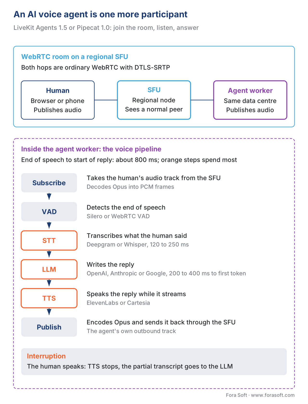 Figure 4. The 2026 voice-agent participant. The agent is just another peer in the SFU; what is novel is the worker's internal pipeline (VAD → STT → LLM → TTS) and the latency budget that pipeline has to live inside.
Comparing the four scaling axes
The patterns above stack: a serious 2026 WebRTC product uses all of them at once, choosing per-room which mix applies. The table below summarises when each axis matters.
| Scaling axis | What it solves | When to add | Typical cost shape | Risk |
|---|---|---|---|---|
| Single SFU, no optimisation | Up to a few hundred participants per room, single region | Day one, MVP | Linear with participants | Single point of failure |
| LastN + simulcast/SVC | O(N²) → O(N) network on dense conferences | First sign of network strain | One-time engineering, then free | None — universal optimisation |
| Cascaded SFU mesh | Multi-region latency, capacity past one box, failover | Past ~500 concurrent participants or any multi-region audience | Per-region SFU cost + inter-node egress | Coordination layer (Redis) becomes a critical dependency |
| SFU-to-HLS bridge | View-only audience past ~5,000 concurrent | When viewers vastly outnumber publishers | CDN egress (cheap) + packager (modest) | Latency tier shifts from 300 ms to 2–5 s for the broadcast audience |
| AI agent worker fleet | Real-time AI participants in calls | When the product roadmap commits to voice agents | GPU compute (the expensive part) + LLM API spend | Latency budget on the agent side becomes a hard constraint |
A common WebRTC-at-scale mistake
The single most common production failure we see when reviewing a WebRTC-at-scale architecture is deploying a cascade without a coordination layer that survives a node failure. The cascade itself is the easy part — every modern SFU ships the primitive. The hard part is the room-state registry that tells every node which other nodes hold participants in which rooms. A single Redis instance in front of a four-region SFU mesh is a single point of failure that defeats the entire point of cascading. The fix is either a Redis cluster with quorum, or an etcd-backed registry, or a distributed-state library like Hazelcast — anything where the loss of one machine in the coordination layer does not freeze the mesh. We have seen architectures where the cascade was perfect and the coordination layer was a single t3.medium instance; when the t3.medium rebooted for security patching at 03:00, every call across four regions dropped. The cascade is a system; the coordination layer is part of the system; you size the coordination layer for the same blast-radius requirement as the SFU fleet.
Free download: WebRTC Scale-Up Pre-Flight Checklist30 items across 6 areas to check before release: single-SFU baseline, LastN and simulcast, cascade design, coordination layer, broadcast bridge and the AI-agent worker fleet.Where Fora Soft fits in
Fora Soft has built WebRTC, conferencing, telemedicine, e-learning, contact-centre video, live-shopping, surveillance, and AR/VR products since 2005 across 239+ shipped projects. The cascaded-SFU pattern is the default architectural choice on every project that crosses a few hundred concurrent participants. The SFU-to-HLS bridge is the standard for live-shopping and telemedicine grand-rounds products where a small panel broadcasts to a wider audience. The AI-agent layer is the newest line of work — LiveKit Agents and Pipecat are now the two stacks the team deploys most often, with the choice driven by whether telephony integration is part of the spec. The Where Fora Soft fits in paragraph in every Block 8 article reflects the same pattern: the verticals are real, the production touchpoints are real, the architectural choices are the ones in this article. In practice that means our WebRTC architecture design team plans the SFU cascade, regional bridges and media-server choice before the first room goes live, and our LiveKit AI agent development practice adds voice and video agents to those rooms with sub-500ms turn-taking.
The book
Video Streaming: A Complete Guide to Video Delivery: From ABR and CDNs to Players, WebRTC, DRM, and the Economics of Streaming
Book 3 takes the scaling story in this article from diagram to design: how SFUs forward, simulcast and pick layers, how a cascade and its coordination layer survive a node failure, and how an LL-HLS bridge and a CDN carry the view-only audience at a price you can plan. Written by Nikolay Sapunov, CEO at Fora Soft.
Will your WebRTC product hold when a room doubles?
Send us your peak room size, regions and whether voice agents are on the roadmap. We will size the SFU nodes, plan LastN and the cascade, check the coordination layer for a single point of failure, and cost the broadcast bridge. 250+ video products shipped since 2005.
See our case studies
Case study
Worldcast Live
HD concerts on WebRTC to 10,000 simultaneous viewers at 0.4–0.5 s latency, with Redis in the stack and quality that adapts to weak connections.
Case study
TransLinguist
mediasoup conferencing for interpreters in 75+ languages, with speech-to-text and text-to-speech working inside the call for AI translation in 16+ languages.
Case study
Sprii
Live shopping: hosts stream over WebRTC or RTMP, buyers watch through Cloudflare and Mux; 72,000+ live events and €365M+ in sales.
What to read next
WebRTC
SFU vs MCU vs Mesh: The Three WebRTC Topologies
The topology background this article builds on.
WebRTC
mediasoup, Janus, LiveKit, Jitsi Videobridge, Pion: Choosing an SFU
Per-vendor capacity numbers and how each one cascades.
WebRTC
Simulcast and SVC: How the SFU Serves a Heterogeneous Audience
The layer choice that makes LastN cheap per subscriber.
Broadcast
Recording, Broadcasting, and the WebRTC-to-HLS Bridge
How SFU frames become CMAF segments for the big audience.
References
- LiveKit — Scaling WebRTC with a Distributed Mesh, LiveKit Engineering, 2024. Vendor engineering blog by the team that built LiveKit; the canonical 2026 reference on cascaded-SFU mesh architecture and the per-region node design. Tier 3.
- LiveKit SFU Internals — official documentation, LiveKit, 2026. Reference documentation for the LiveKit SFU's distributed-mesh routing, Redis coordination, and worker dispatcher. Tier 3.
- LiveKit Agents — official documentation, LiveKit, 2026. The reference for the Agents 1.5 framework, VoicePipelineAgent, MCP tool support, and adaptive interruption. Tier 3.
- Pipecat — official documentation, Daily.co, 2026. The 1.0 release notes (April 14, 2026), processor model, and WebRTC/SIP transport adapters. Tier 3.
- LiveKit blog — A tale of two protocols: WebRTC vs HLS for live streaming, LiveKit, 2024–2026. The trade-off matrix for the SFU-to-HLS bridge architecture in 2026. Tier 3.
- Politis, Tsioutas, Mavridis — Last N: Relevance-Based Selectivity for Forwarding Video in Multimedia Conferences, NOSSDAV 2015. The reference paper for the LastN scheme and the 45%/63% CPU/bandwidth saving numbers. Tier 5 (peer-reviewed academic).
- RFC 6464 — A Real-time Transport Protocol (RTP) Header Extension for Client-to-Mixer Audio Level Indication, Lennox, Ivov, Marocco, December 2011. Standards-track. The RTP audio-level header extension dominant-speaker identification depends on. Tier 1.
- RFC 8825 — Overview: Real-Time Protocols for Browser-Based Applications, Alvestrand, January 2021. Standards-track. The WebRTC architecture overview RFC. Tier 1.
- RFC 8835 — Transports for WebRTC, Alvestrand, January 2021. Standards-track. The transport requirements for WebRTC media; cited for inter-node transport choices in the cascade. Tier 1.
- mediasoup — Pipe Transport documentation, mediasoup project, 2026. Reference for the mediasoup primitive used to build a cascade across mediasoup instances. Tier 3.
- Jitsi Videobridge — Octo overview, Jitsi project, 2024. The reference for Jitsi's cascaded-SFU implementation. Tier 3.
- Cloudflare Realtime — official documentation, Cloudflare, 2026. Vendor documentation for the cascaded-edge SFU product, including the inter-edge backbone transport. Tier 3.
- OpenAI Realtime API — official documentation, OpenAI, 2026. Reference for the speech-in/speech-out API that LiveKit Agents and Pipecat both wrap. Tier 3.
