


Why This Matters
Streaming feels invisible when it works and impossible to debug when it doesn't, because the thing the viewer complains about ("the stream froze") is almost never where the problem actually lives. The root cause sits at one of nine stages somewhere between a camera and a screen, and you cannot locate it without a mental map of those stages. We wrote this article for the founder scoping a live shopping app, the product manager arguing with an encoder vendor, and the engineer who built the player but never had to think about origin shielding. By the end you will be able to point at any frozen, buffering, or laggy stream and name the three likeliest stages to blame, in priority order, with reasons. This is also the article every later piece in our Learn hub circles back to: every block reuses the same map and zooms into one part of it.
The map you will keep coming back to
A live streaming pipeline has nine stages. They run strictly left to right in time: each stage hands its output to the next, and a problem at stage n always shows up at stage n + 1 and later, never earlier. The stages, in order:
- Capture — the sensor and lens turning photons into a raw frame buffer.
- Encode — the encoder compressing the raw frames into a coded bitstream.
- Contribution (ingest) — the protocol carrying the encoded bitstream from the venue to the cloud.
- Transcode — the cloud-side encoder rebuilding the stream into multiple resolutions and bitrates.
- Package — the wrapping of those bitrates into segments and a manifest the player can read.
- Origin — the storage and HTTP front for the packaged segments and manifest.
- CDN — shield, mid-tier, edge — the multi-tier cache hierarchy that absorbs viewer demand without overloading the origin.
- Last-mile network — the home Wi-Fi, mobile cell, satellite link the viewer is actually on.
- Player — the application that fetches segments, decodes frames, and paints them on the screen.
Every streaming product on the planet — Netflix, Twitch, YouTube Live, your local OTT app, a corporate webinar — uses this same nine-stage shape. What differs across products is which protocols run on each leg, how aggressively each stage is tuned for latency vs. cost, and where the failure budget is spent. The rest of the article walks the stages in order, and then closes with two worked examples that show the same pipeline tuned for two very different jobs.
 Figure 1. The end-to-end streaming pipeline. Nine stages, each with a typical protocol on the leg in and out, and a typical latency contribution. This diagram is the spine of the entire Learn hub — every later article zooms into one box.
Stage 1 — Capture
Capture is the stage most readers picture when they hear "streaming" and the one least well understood. The camera's image sensor — a grid of tiny photo-sites called pixels — converts light into an electrical signal forty, fifty, sometimes sixty times a second. The signal is read out as a raw frame buffer: a two-dimensional array of pixel values, several megabytes each, completely uncompressed. A 1080p frame at 30 frames per second produces about 187 megabytes per second of raw data; a 4K frame at 60 fps closer to a gigabyte per second.
You cannot stream the raw output. Two hundred megabytes per second saturates a household fibre line; a gigabyte per second saturates a small office. The job of every later stage is to get that raw firehose down to something a viewer's connection can swallow — typically 3 to 8 Mbps — while preserving as much visual quality as possible. The capture stage is what sets the upper bound on how good the stream can ever look, because nothing downstream invents detail the sensor never recorded.
The latency contribution at capture is small but real: roughly one frame interval, or 16 to 33 ms for 30 to 60 fps sources, between a photon arriving at the sensor and a frame buffer being handed to the encoder. The dominant failure modes are unrelated to streaming — bad focus, wrong exposure, motion blur — but they show up downstream as "the stream looks bad" complaints that no protocol choice can fix.
A useful analogy: capture is like a stenographer writing every word a speaker says, in full longhand, every second. The transcription is perfect and unmanageable. Every later stage is an abbreviation system that gets the message across without anyone copying every word.
Stage 2 — Encode
The encoder is the first stage that does compression, and its job is to turn the raw firehose into something the network can carry. Modern video encoders — H.264 (AVC), H.265 (HEVC), AV1, the experimental H.266 (VVC) — use a single trick repeatedly: instead of describing each frame from scratch, describe how each frame differs from the previous one. Most frames in a video are mostly the same as the frame before, so the difference is small, and a small difference compresses to a small number of bytes.
A few frames every couple of seconds are described in full: these are the keyframes (technically IDR frames in H.264 / HEVC parlance, or IRAP frames more generally). Between two keyframes the encoder produces predicted frames (P-frames and B-frames) that reference earlier frames in the sequence. The whole bundle between two keyframes is called a GOP (Group of Pictures), and its length — the keyframe interval — is the encoder's single most important streaming setting.
The convention in 2026 is a GOP length of 2 seconds. The Apple HLS Authoring Specification revision 2025-09 has required this exact value since 2018; the DASH-IF Low-Latency Live guidelines (revision 4.3) align with it; every major encoder vendor — AWS Elemental, Bitmovin, Wowza, NVIDIA — ships with 2-second GOPs as the default for streaming presets. A 2-second GOP means a keyframe every 60 frames at 30 fps, every 120 frames at 60 fps, and a clean cut point for the next stage (packaging) to split the stream into segments.
The math out loud, for the first time. A 1080p 30 fps stream from an H.264 encoder at a typical bitrate of 5 Mbps produces:
- 5,000,000 bits/sec ÷ 8 bits/byte = 625,000 bytes/sec = 625 KB/sec of compressed bitstream;
- 30 frames/sec × 2 sec/GOP = 60 frames per GOP;
- one keyframe and 59 predicted frames per GOP;
- the keyframe is roughly 5 to 10× the size of an average predicted frame, so a typical GOP is about 1.25 MB.
The encoder's latency contribution is the most variable in the pipeline. A real-time encoder running on a recent GPU produces output within one frame interval of input — 16 to 33 ms — using a single-pass setting. A high-quality VOD encoder running multi-pass takes seconds or minutes per frame, which is fine for VOD and fatal for live. Vendor presets called low-latency, normal-latency, and very-low-latency exist on every encoder to expose this dial.
Common mistake to avoid: setting the GOP to a value the packager downstream cannot align with. If the segment length is 6 seconds and the GOP is 5 seconds, every other segment misses its keyframe and the player has to fetch the segment before to start decoding. Keep GOP and segment length aligned — 2 second GOP with 2 or 4 or 6 second segments — and the rest of the pipeline runs cleaner.
Stage 3 — Contribution (ingest)
Contribution is the leg between the encoder and the cloud. It is the riskiest hop in the whole pipeline, because the network between a venue and the cloud is typically the worst-conditioned link in the chain — a single home internet connection, a 4G hotspot, a tournament venue's overloaded Wi-Fi. Whatever protocol carries the encoded stream over this hop has to defend itself against jitter, loss, and the occasional total link drop.
Three protocols dominate the 2026 contribution landscape:
- RTMP (Real-Time Messaging Protocol) — the legacy default. Adobe-defined, TCP-based, runs on port 1935, ships on every encoder ever shipped, end-of-lifed by Adobe but kept alive by every OBS and Streamlabs install. RTMP works, but it has no real congestion control, no native UDP path, and no support for codecs beyond H.264 + AAC. We have an entire article on its 2026 status.
- SRT (Secure Reliable Transport) — the professional contribution standard for the public internet, defined by an active IETF Internet-Draft,
draft-sharabayko-srt-NN. UDP-based with tunable forward error correction and automatic repeat request, supports any codec, and is what most broadcast remotes use today. Adds about 4× the round-trip time of latency as the configurable buffer for loss recovery. - WHIP (WebRTC-HTTP Ingest Protocol) — the modern standard, IETF RFC 9725, published March 2025. A thin HTTP signalling layer on top of WebRTC for ingest. Sub-second latency, runs through firewalls, ships in every modern encoder. The right default for any new pipeline starting in 2026 unless you have a specific reason not to.
Two niche standards round out the picture: RIST (SMPTE TR-06) for broadcast-grade contribution, and ST 2110 / NDI for the studio-internal leg where everything is on a controlled gigabit LAN. We cover the full picture in Picking an ingest protocol in 2026.
Contribution latency depends entirely on the protocol. WHIP adds 100 to 500 ms. SRT adds the configured buffer — typically 1 to 4 seconds. RTMP adds the TCP retransmission tail, anywhere from 200 ms to 8 seconds depending on packet loss. The dominant failure modes are link drops (the camera moves out of Wi-Fi range), bandwidth exhaustion (the venue's uplink saturates), and encoder-side buffer overruns (the encoder produces faster than the link can move).
A practical heuristic for sizing contribution bandwidth: budget for 1.5× the encoded bitrate of the highest-quality rendition you ship. A 5 Mbps stream needs a 7.5 Mbps sustained uplink. The 50% headroom absorbs protocol overhead, retransmission bursts, and the periodic keyframe spikes that the GOP produces.
Stage 4 — Transcode
The transcoder is the cloud-side encoder that takes the single inbound contribution feed and rebuilds it into the bitrate ladder — the menu of resolutions and bitrates the player will pick from. A typical 2026 ladder for live streaming has five rungs: 1080p at 5 Mbps, 720p at 3 Mbps, 480p at 1.5 Mbps, 360p at 0.8 Mbps, 240p at 0.4 Mbps. The viewer's player picks the rung their connection can sustain and switches rungs every couple of seconds as conditions change.
Transcoding is computationally expensive — each rung is a full H.264 / HEVC / AV1 encode, running in real time, on GPU or specialised ASIC. A live 5-rung ladder at 1080p typically consumes 0.5 to 2 vCPU-equivalents per stream, depending on the codec and the encoder vendor. AV1 transcoding consumes 5 to 10× more than H.264 transcoding for the same quality target as of 2026 silicon, which is why AV1 ladders are still rare in live and routine in VOD.
The transcoder is where two of the most important production decisions get made. The first is the bitrate ladder shape — how many rungs, what resolutions, what bitrates — which we cover in Building a bitrate ladder. The second is codec selection: every rung in the ladder must be encoded in every codec the player population can decode. A 2026 OTT product typically ships its ladder in both H.264 (universal compatibility) and either HEVC or AV1 (efficiency on supported devices), doubling the transcoder cost.
Transcode latency is the second-largest contributor in the whole pipeline, after player buffer. A well-tuned real-time transcoder adds 200 to 800 ms — one segment's worth of work — to the glass-to-glass total. A poorly tuned one (multi-pass settings on a live source) can add 5 to 30 seconds, and is the single most common cause of "why is my live stream 30 seconds behind?" complaints.
A common pitfall: running transcode in software on general-purpose CPU when you have GPU or ASIC available. NVIDIA NVENC, Intel Quick Sync, and dedicated ASICs like AMD's Alveo MA35D do the same job at 5 to 50× lower power and lower latency. If the transcode bill is hurting and the latency budget is tight, this is the first place to look.
Stage 5 — Package
The packager wraps the transcoded bitstreams into the file format the network and the player understand. It does three things: splits each rung's bitstream into segments (short, independently-decodable chunks); writes a manifest that lists those segments and their bitrates; and stores both on the origin.
In 2026 the dominant package format is CMAF (Common Media Application Format, ISO/IEC 23000-19:2024). CMAF is a fragmented MP4 (fMP4) container designed so the same physical segment can be served by both HLS and DASH — one set of media files, two manifests. Before CMAF, packaging produced separate MPEG-TS segments for HLS and fMP4 segments for DASH, doubling storage and complicating cache keys. CMAF is the unification.
The packager produces:
- Per rung, a sequence of media segments —
video_1080p_00001.m4s,video_1080p_00002.m4s, … — each 2 to 6 seconds of presentation time, starting with a keyframe. - A manifest that lists the segments and the renditions. For HLS, this is an
.m3u8playlist, a plain-text file with#EXT-tags. For DASH, it is an.mpd, an XML document. CMAF lets one segment serve both manifests. - An init segment per rung —
init_1080p.mp4— that carries the codec configuration and is downloaded once at startup.
Segment length is the single biggest knob the packager exposes. A 6-second segment has lower overhead and better caching but higher latency. A 2-second segment is what every modern low-latency pipeline ships. A 200 ms CMAF chunk inside a 2-second segment is what low-latency HLS and low-latency DASH use to push end-to-end latency below 5 seconds without sacrificing segment boundaries. We dig into segments and chunks in LL-HLS in depth and LL-DASH and low-latency CMAF.
The packager's latency contribution is small when configured for low-latency CMAF: 200 to 500 ms. When configured for classic HLS with 6-second segments, it adds 6 to 18 seconds (one to three segment durations the player must buffer before starting). This is why "classic HLS" and "low-latency streaming" are different products built from the same packager.
Common mistake: shipping a manifest with no EXT-X-INDEPENDENT-SEGMENTS tag, leaving the player guessing whether each segment is decodable on its own. The Apple HLS Authoring Specification revision 2025-09 lists this tag as required for low-latency HLS; many packagers still default it off.
Stage 6 — Origin
The origin is the HTTP server that serves the manifest and segments to whatever asks for them. In a small streaming product the origin is a single bucket — an AWS S3 bucket, a Google Cloud Storage bucket, a Backblaze B2 bucket — fronted by a thin HTTP layer that handles range requests and content negotiation. In a large one the origin is a cluster of servers with replication, multi-region storage, and just-in-time packaging for less popular renditions.
The origin's job sounds simple — answer GET requests with the right segment — and the implementation is anything but. The 2026 production origin handles:
- Live recording windows: a live stream's segments expire after a few minutes; the origin holds a rolling window of the last N segments and discards older ones, unless DVR is enabled, in which case it holds hours.
- Just-in-time packaging: instead of pre-packaging every rung in every protocol, store the source mezzanine once and produce manifests on demand. Saves storage, adds CPU.
- Token-authenticated URLs: every segment URL carries a signed token so the CDN edge can refuse unauthorised viewers. The Apple HLS spec, AWS CloudFront, Akamai EdgeAuth, and Cloudflare Signed URLs all use the same pattern.
- Cache-control headers: the manifest gets short cache-control (1 to 2 seconds) so the player sees new segments; the segments themselves get long cache-control (hours) because they never change once written.
The origin is the only part of the pipeline that holds the stream. Every other stage either produces or consumes; the origin is the buffer the rest of the pipeline points at. When viewers complain that "yesterday's stream is gone", the origin's retention window is the answer.
Origin latency contribution is small in normal operation — the storage-read time for the requested segment, typically 20 to 100 ms — but climbs sharply when the cache hierarchy fails and millions of viewers hit the origin simultaneously. This is precisely what the next stage exists to prevent.
Stage 7 — CDN: shield, mid-tier, edge
A content delivery network is the multi-tier cache hierarchy that absorbs viewer demand without overloading the origin. The hierarchy is the part of the pipeline that took streaming from a 1,000-viewer demonstration in 2007 to a 200-million-viewer simultaneous live event in 2024.
A modern CDN runs three or four tiers between the viewer and the origin:
- Edge — the layer closest to the viewer. Roughly 300 to 600 edge points of presence (PoPs) per major CDN in 2026, scattered across cities. The edge answers the viewer's request directly; cache hits return in 10 to 50 ms.
- Mid-tier — a regional cache layer between edge and shield. Edge cache misses go to mid-tier; mid-tier has larger storage and longer retention than the edge.
- Shield (origin shield) — a single regional aggregation cache that sits between the CDN and the origin. The shield's job is to make sure the origin sees only one request per segment per region, no matter how many edges are asking. AWS CloudFront calls this Origin Shield; Cloudflare calls it Tiered Cache; Google Media CDN calls it the origin shield tier. The numbers are striking: origin shield reduces origin requests by 90 to 95% during live events.
A typical request flow on a cache miss: viewer's player asks edge → edge asks mid-tier → mid-tier asks shield → shield asks origin → origin returns segment → segment caches at shield, mid-tier, and edge on the way back to the viewer. The next 100,000 viewers in the same region all hit the edge directly; the origin sees one request, total.
The arithmetic of why this matters. A 50,000-viewer live stream pushes 5 Mbps per viewer, for 250 Gbps of aggregate egress. If every viewer hit the origin directly, the origin would need 250 Gbps of network capacity and the storage IOPS to match. With a properly configured shield in front, the origin sees one fetch per segment per region — perhaps 10 fetches per second across 6 regions, for 50 Mbps of origin egress. The CDN turns a 250 Gbps origin problem into a 50 Mbps origin problem.
The CDN's latency contribution is small on cache hits (10 to 50 ms) and large on cold-cache misses (100 to 500 ms while the request walks up the tiers and back). For live streaming, the first viewer of a new segment in each region pays the cold-cache cost; everyone after pays nothing. We cover the architecture in Origin shielding and tiered caching and the cost economics in CDN cost economics.
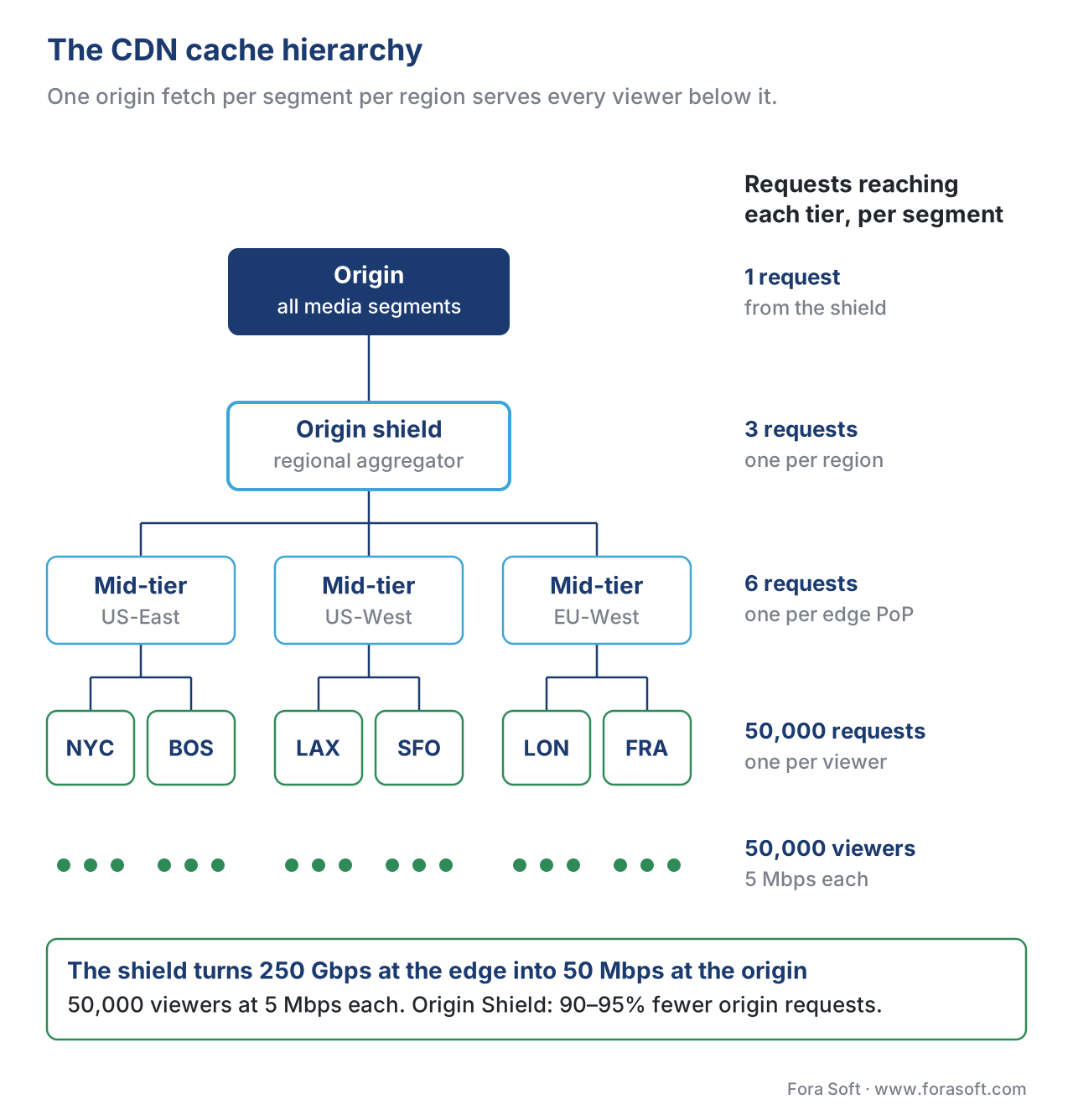 Figure 2. The CDN cache hierarchy. One request to origin per region serves every viewer in that region. The shield is what makes million-viewer events affordable.
The single most expensive CDN failure mode is a cache key mismatch — when two viewers ask for the same segment but the CDN treats them as different requests because their URLs differ in a query string. A 95% cache hit rate plunges to 5%, the origin saturates, the stream falls over. Every CDN team learns this lesson the hard way once. The fix is canonical URL discipline plus careful cache-key configuration, which we cover in Cache keys for streaming.
Stage 8 — Last-mile network
The last-mile network is the leg from the CDN edge to the viewer's device — the cable modem, the fibre ONT, the cellular radio, the Wi-Fi access point. It is the only stage in the pipeline the streaming engineer does not control. It is also where most of the failures actually show up, because home internet is the most variable link in the chain.
A 2026 viewer's last mile is one of:
- Fixed-line broadband (DOCSIS cable, GPON fibre) — typically 50 to 1000 Mbps, low jitter, occasional bufferbloat during congestion.
- Mobile (4G LTE, 5G mid-band, 5G mmWave) — typically 5 to 300 Mbps, high jitter, occasional total loss during handover.
- Wi-Fi (Wi-Fi 6, Wi-Fi 7) — between the modem and the device, contributes its own losses. A 1.2 Gbps fibre link drops to 50 Mbps at the device if the Wi-Fi access point is two walls away.
- Satellite (Starlink) — 70 to 200 Mbps median in 2025 deployments, sub-50 ms RTT, but with 1 to 3 second gaps during satellite handover that segmented streaming absorbs and real-time streaming chokes on.
The last mile's latency contribution is dominated by round-trip time: 5 to 30 ms on fixed-line, 20 to 100 ms on mobile, 30 to 60 ms on Starlink. The throughput contribution is whatever the connection sustains at the moment the player asks. We cover the network reality in detail in Bandwidth, throughput, jitter, packet loss and the last-mile reality in Mobile, satellite, 5G, Wi-Fi 6/7.
What the pipeline does about the last mile: the adaptive bitrate ladder. The viewer's player measures the throughput it observed on the last segment download and picks the rung of the ladder whose bitrate fits inside that throughput. When the throughput drops, the player steps down a rung within one segment fetch. The ladder is the pipeline's defence against the last mile, and the reason a 1.5 Mbps mobile viewer and a 25 Mbps fibre viewer can watch the same live event from the same CDN.
Stage 9 — Player
The player is the application on the viewer's device — a browser tab running hls.js, an iOS app calling AVPlayer, a smart-TV embedded WebKit running Shaka — that fetches segments, decodes frames, and paints them on the screen. From the pipeline's perspective the player is the consumer; from the user's perspective the player is the whole thing.
The player's job has five parts, in order:
- Fetch the manifest — download the
.m3u8or.mpd, parse the list of renditions and segments. - Pick a starting rendition — usually the lowest rung, so playback starts fast, then climb the ladder once the buffer fills.
- Build a buffer — fetch the next few segments ahead of the play head and store them in memory. The Apple HLS Authoring Specification requires the buffer be at least 3× the target segment duration before starting playback.
- Decode — feed segments to the platform's hardware decoder, get back raw frames, paint at the display refresh rate.
- Adapt — every couple of seconds, measure observed throughput and pick a new rendition if the conditions changed.
The player's latency contribution is the largest of any stage in classic HLS pipelines. A 6-second segment duration with the spec-required 3-segment hold-back produces an 18-second floor on glass-to-glass latency. A 2-second segment with a 3-segment hold-back drops the floor to 6 seconds. A 2-second segment with low-latency HLS (200 ms CMAF chunks, partial segment fetches, blocking playlist reloads) drops the floor to 2 to 5 seconds. A WebRTC pipeline with no segments at all drops to 200 to 500 ms — but at the cost of giving up the HTTP cache hierarchy.
The major web players in 2026 are hls.js (5.8M weekly downloads, the de-facto HLS player for non-Safari browsers, covered in hls.js in depth), Shaka Player (Google, used inside YouTube's player and for any pipeline that needs both DASH and HLS, covered in Shaka Player in depth), and dash.js (the DASH reference implementation). On Apple devices Safari plays HLS natively via AVPlayer. Smart TVs each run their own embedded player; we cover the matrix in Smart TV players.
Common mistake: optimising the encoder, packager, and CDN for low latency and then shipping a player on its default settings. A well-tuned hls.js can get an LL-HLS pipeline under a second of latency; an out-of-the-box hls.js on the same feed sits closer to 6 seconds. The player is the last stage and the biggest single lever on perceived latency.
Where it all adds up: the latency budget
Pull the nine stages together and you get the glass-to-glass latency budget — the time between a photon hitting the camera sensor and the same photon's representation appearing on the viewer's screen. Three numbers worth memorising for 2026, drawn from the Apple specification, the DASH-IF guidelines, and production deployments:
| Pipeline configuration | Typical glass-to-glass | Used for |
|---|---|---|
| Classic HLS, 6 s segments, 3-segment hold-back | 18–30 s | OTT VOD-like live (news, talk shows) |
| Low-latency HLS / DASH, 2 s segments, 200 ms chunks | 2–5 s | Live sports, interactive live shopping |
| WebRTC delivery (WHEP / SFU) | 0.2–0.5 s | Auctions, interactive Q&A, conferencing |
 Figure 3. Where the seconds go. The player buffer is the dominant stage in every HTTP-based pipeline; WebRTC removes it entirely.
Two worked examples
Concrete is better than abstract. Two real pipelines, each with the same nine stages but tuned for different jobs.
Example A — OTT live event, 500,000 concurrent viewers
A national football league broadcasts a match on its own OTT app. Target glass-to-glass latency: 4 to 8 seconds (close enough to broadcast TV that a viewer watching the app does not get spoilers from a neighbour watching cable). Audience: 500,000 concurrent at peak, mixed devices, predominantly mobile.
- Capture: stadium camera array, output via SDI to encoder room.
- Encode: stadium encoder, H.265, 2-second GOP, single-pass real-time.
- Contribution: SRT over 1 Gbps point-to-point link from stadium to cloud. 2-second buffer for retransmission.
- Transcode: cloud transcoder, 6-rung ladder (1080p / 720p / 480p / 360p / 240p / audio-only) in both H.264 and HEVC.
- Package: CMAF, 2-second segments, 200 ms chunks. HLS manifest + DASH manifest sharing the same media files.
- Origin: AWS S3 with rolling 4-hour window for DVR scrub-back.
- CDN: Akamai or Cloudflare with Origin Shield enabled. Edge POPs in every major city of the country.
- Last-mile: viewers on mobile, home fibre, public Wi-Fi.
- Player: hls.js in browsers, AVPlayer on iOS, ExoPlayer on Android, native on smart TVs.
Glass-to-glass: 4 to 6 seconds. Cost driver: CDN egress at 2.5 Tbps peak. Failure budget: spend most of it on encoder + CDN resilience; the contribution link is short and direct.
Example B — Telemedicine consultation, 1-to-1
A patient at home video-calls a doctor through a telemedicine platform. Target glass-to-glass latency: under 400 ms (conversation breaks down past that). Audience: 1 viewer, both directions, full duplex.
- Capture: laptop or phone camera, raw YUV frames.
- Encode: WebRTC's encoder, H.264 / VP9 / AV1 depending on devices, 1-second GOP, single-pass real-time, simulcast or SVC for layered quality.
- Contribution: WebRTC peer connection direct or via TURN relay, no separate ingest stage — the encoder talks to the SFU directly. ICE / STUN / TURN for NAT traversal.
- Transcode: usually none; the SFU forwards the layers without re-encoding. SVC selection at the SFU rather than per-rung transcoding.
- Package: none in the streaming sense; RTP packets carry the encoded frames.
- Origin: the SFU itself, in the cloud, region-pinned for low RTT to both parties.
- CDN: a global SFU mesh, with media servers in each region; the patient and doctor connect to the nearest SFU.
- Last-mile: same Wi-Fi or mobile as Example A but with stricter loss and jitter budgets.
- Player: the WebRTC stack inside the browser or mobile SDK — no separate player application.
Glass-to-glass: 200 to 400 ms. Cost driver: SFU compute, not egress. Failure budget: spend most of it on bandwidth estimation, FEC, and TURN-relay fall-back. We cover the topology in SFU vs MCU vs Mesh and the bandwidth estimation in WebRTC bandwidth estimation.
Same nine stages. Different tunings, different protocols, different cost structure. The pipeline shape is the constant; the protocol and parameter choices vary by job.
Common mistakes across the whole pipeline
A few errors recur across every kind of streaming product, and naming them up front saves teams from spending sprints chasing them.
Treating the pipeline as one black box. When the stream is slow or freezes, the temptation is to blame "the streaming". The right move is to walk the pipeline left to right and ask which stage's metrics are bad. The encoder reports its output bitrate and queue depth. The CDN reports its hit rate and origin egress. The player reports its buffer health and rebuffer count. The stage with the bad metric is the one that needs fixing.
Optimising one stage in isolation. Buying a faster encoder helps nothing if the player is still buffering 18 seconds. Switching to AV1 saves CDN bandwidth but burns transcode CPU. Every stage interacts with its neighbours; optimisations that don't reckon with the whole budget often just move the problem along the pipeline.
Missing keyframe alignment. The GOP length set at the encoder, the segment length set at the packager, and the chunk length set at LL-HLS must all be integer multiples of each other or the pipeline produces wasted bandwidth and player stalls. The 2-second GOP / 2-second segment / 200 ms chunk combination is the convention specifically because the math works out cleanly.
Ignoring the player's defaults. Every other stage is engineered carefully and the player gets shipped on whatever the framework defaults are. The player is the last and biggest latency lever; treat its configuration as a first-class production setting.
Sizing for the top rendition. Most viewers will not watch your top rendition. They will watch the rendition their connection sustains, weighted by device. Size your CDN egress and your origin storage for the realistic mix, not for the 4K headline.
Free download: Streaming Pipeline MapOne printable page with the nine stages of a 2026 streaming pipeline, the typical protocol on each leg and the latency each stage adds, so you can find the stage to blame before you open a dashboard.Where Fora Soft Fits In
We have shipped streaming and real-time media stacks since 2005, across video conferencing, OTT and Internet TV, telemedicine, e-learning, video surveillance, and AR/VR. The nine-stage pipeline in this article is the daily work: contribution-side WHIP and SRT ingests for OTT live events; transcoder ladders and CMAF packaging for catalogue-grade OTT; CDN architecture and Origin Shield design for million-viewer concurrent peaks; WebRTC SFU topologies for the telemedicine and conferencing side of the catalogue. We test every product against a written latency budget in lab before it ships, because the alternative is debugging the same problem live in production at peak. That pipeline work ships as video and audio streaming software development and, for catalogue and live-channel products, as OTT and Internet TV platforms for web, mobile and Smart TV.
The book
Video Streaming: A Complete Guide to Video Delivery: From Network Protocols and Transport to Ingest, HLS, and MPEG-DASH
This article draws the nine-stage map. Book 2 walks its first half in depth: how the network treats a stream, how RTMP, SRT, RIST and WHIP carry it from the venue, how packaging turns the ladder into HLS and MPEG-DASH, and how the glass-to-glass budget adds up stage by stage. Written by Nikolay Sapunov, CEO at Fora Soft.
Which stage of your pipeline is eating the latency?
Send us your stack from camera to player: encoder, ingest protocol, ladder, packager, CDN and player settings. We will write the latency budget stage by stage, point to the two or three stages that cost you the most, and tell you what changing them costs. 250+ video products shipped since 2005.
See our case studies
Case study
Worldcast Live
HD concerts at 0.4–0.5 s glass-to-glass for 10,000 simultaneous viewers at 1.5 Gb/s: the WebRTC end of the latency chart, with no player buffer to hide behind.
Case study
CirrusMed
Browser-based telemedicine for a practice licensed in 48+ U.S. states: 1-to-1 WebRTC video visits, the same nine stages tuned for a conversation, as in Example B.
Case study
Mindbox
Video management across 50+ sites: RTSP camera feeds pulled through FFmpeg into HLS, a full capture-to-player pipeline where every stage has to hold up.
What to read next
Latency
Latency, Glass-to-Glass, End-to-End: What the Seconds Actually Mean
The latency budget applied to every stage on this map.
Protocols
The Delivery Protocol Family Tree
Which protocol lives on which leg of the pipeline.
CDN
Origin Shielding and Tiered Caching
How stage 7 turns 50,000 requests into one.
Calculator
Latency Budget Calculator: Add Up the Seconds Before You Pick a Protocol
Put your own numbers into the nine-stage sum.
References
- Pantos, R., May, W. RFC 8216: HTTP Live Streaming. IETF, August 2017. The canonical HLS specification; cited here for segment and manifest structure, the EXT-X-* tag family, and the player buffer / hold-back rules. https://datatracker.ietf.org/doc/html/rfc8216
- Pantos, R. (ed.) draft-pantos-hls-rfc8216bis-22: HTTP Live Streaming 2nd Edition. IETF Internet-Draft, April 2026. The successor RFC currently under IESG review; consolidates LL-HLS extensions into the base specification. Cited as in-progress with the explicit note that the draft is subject to revision. https://datatracker.ietf.org/doc/html/draft-pantos-hls-rfc8216bis
- Apple Inc. HTTP Live Streaming (HLS) Authoring Specification for Apple Devices, revision 2025-09. Apple Developer Documentation, September 2025. Source of the 2-second GOP convention, the EXT-X-INDEPENDENT-SEGMENTS requirement, the BANDWIDTH peak-vs-average rule, and the 3-segment buffer minimum. https://developer.apple.com/documentation/http-live-streaming/hls-authoring-specification-for-apple-devices
- ISO/IEC 23000-19:2024. Information technology — Multimedia application format (MPEG-A) — Part 19: Common media application format (CMAF) for segmented media. ISO/IEC, 2024 edition. The CMAF specification that defines the fMP4 container, the chunk structure, and the brand profiles cited in the packaging section.
- ISO/IEC 23009-1:2022. Information technology — Dynamic adaptive streaming over HTTP (DASH) — Part 1: Media presentation description and segment formats. ISO/IEC, 2022 edition. The DASH specification, cited here for the MPD manifest structure and the SegmentTemplate / SegmentTimeline distinction.
- Murillo, S., Naranjo, Ch., Tarrías, G., Murillo, J. RFC 9725: WebRTC-HTTP Ingestion Protocol (WHIP). IETF, March 2025. The standards-track specification for WebRTC-based contribution. Cited here as the default ingest protocol recommendation for 2026 pipelines. https://datatracker.ietf.org/doc/html/rfc9725
- Iyengar, J., Thomson, M. (eds.) RFC 9000: QUIC: A UDP-Based Multiplexed and Secure Transport. IETF, May 2021. Cited here for the transport layer underlying HTTP/3, on which modern manifest fetches and chunk delivery run. https://datatracker.ietf.org/doc/html/rfc9000
- DASH Industry Forum. DASH-IF Implementation Guidelines: Low-Latency Live Streaming, revision 4.3. DASH-IF, March 2026. Industry de-facto profile for low-latency DASH and CMAF chunked encoding. Cited for the chunk-length and segment-length recommendations. https://dashif.org/docs/CR-Low-Latency-Live-r8.pdf
- AWS. Amazon CloudFront Origin Shield — Developer Guide. Amazon Web Services, May 2026. Cited here for the Origin Shield architecture and the 90 to 95% origin-load reduction figure. https://docs.aws.amazon.com/AmazonCloudFront/latest/DeveloperGuide/origin-shield.html
- Cloudflare. Tiered Cache documentation. Cloudflare developer docs, 2026. Cited for the mid-tier / edge architecture and the cache-key discipline in the CDN section. https://developers.cloudflare.com/cache/how-to/tiered-cache/
- Google Cloud. Media CDN — Origins overview. Google Cloud documentation, 2026. Cited for the origin shield tier and the cache hierarchy descriptions. https://docs.cloud.google.com/media-cdn/docs/origins
- SMPTE. TR-06-1, TR-06-2, TR-06-3: Reliable Internet Stream Transport (RIST) Protocol Specification. SMPTE, 2020–2024. Cited in the contribution section as the broadcast-grade alternative to SRT.
- Schulzrinne, H., Casner, S., Frederick, R., Jacobson, V. RFC 3550: RTP: A Transport Protocol for Real-Time Applications. IETF, July 2003. Cited for the RTP transport that WebRTC uses on the last-mile leg.
- AWS. How to configure a low-latency HLS workflow using AWS Media Services. AWS Media Blog. Vendor reference for the LL-HLS chunk and partial segment configuration cited in the packaging section. https://aws.amazon.com/blogs/media/how-to-configure-a-low-latency-hls-workflow-using-aws-media-services/
- Survey paper: Bentaleb, A. et al. An End-to-End Pipeline Perspective on Video Streaming in Best-Effort Networks: A Survey and Tutorial. ACM Computing Surveys, 2024. Academic survey of the full streaming pipeline, used here as a cross-check on stage decomposition. https://dl.acm.org/doi/10.1145/3742472
